
System Interface
High Capacity Appliance Interface
There are several LEDs on the control panel and on the drive carriers to keep you constantly informed of the overall status of the system.
This chapter explains the meanings of all LED indicators and the appropriate response you may need to take.
LED Indicators
Control Panel Button
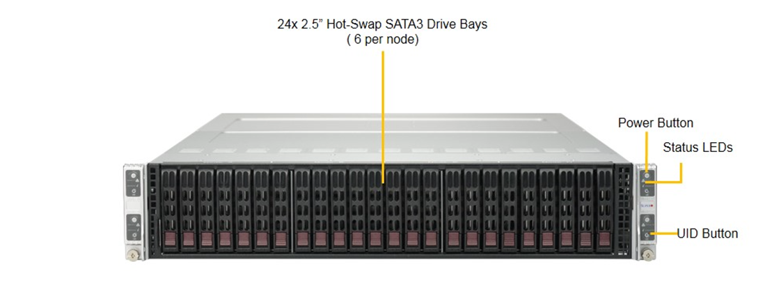
Power
The main power button on each of the four control panels is used to apply or remove power from the power supply to each of the four server nodes in the chassis.
The power button has a built-in LED which will turn green when the power is on.
Each of the four server nodes are powered on and off individually.
Powering off one server node does not affect the power of the other server nodes.
Turning power off with this button does not remove power from the chassis, hence caution must be used when servicing.
UID
The UID button is used to turn on or off the blue light function of the LED.
Once the blue light is activated, the unit can be easily located in very large racks and server banks.
Control Panel LEDs
The four control panels are located on the front handle of the chassis.
Each control panel has two additional LEDs.
These LEDs provide you with critical information related to different parts of the system.
This section explains what each LED indicates when illuminated and any corrective action you may need to take.
Alert
This LED is illuminated when an alert condition occurs:
•A solid red light indicates an overheat condition in the system
•A flashing red light which flashes in one second intervals indicates a fan failure
•A flashing red light which flashes in four second intervals indicates a power failure
When notified of an alert, check the routing of the cables and make sure all fans are present and operating normally.
You should also check to make sure that the chassis covers, and air shrouds are installed.
This LED will remain flashing or on as long as the temperature is too high, or a fan does not function properly.
NIC
Indicates network activity on either LAN1 or LAN2 when flashing.
Drive Carrier LEDs
SATA Drives
Each drive carrier has two LEDs.
•Blue: When illuminated, this blue LED (on the front of the drive carrier) indicates drive activity. A connection to the back-plane enables this LED to blink on and off when that drive is being accessed
•Red: The red LED to indicate a hard drive failure.