
About IGMP Snooping Support with VXLAN
Starting with version 3.1.1, Netvisor ONE adds support for selective replication of (instead of always flooding) multicast traffic based on IGMP join messages received over ports and tunnels.
With this enhancement multicast traffic belonging to a group is forwarded only to member ports and relevant remote VTEPs.
This feature uses the head-end replication (HER) model for replication of packets to be sent over to remote VTEPs. Netvisor ONE also forwards IGMP join messages over VXLAN tunnels, for other fabric switches to see those messages and as a consequence build the group membership list accordingly.
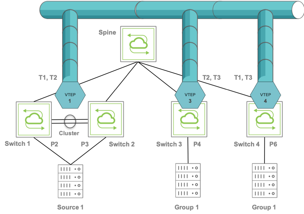
Figure 8-12: Example of Fabric Topology with Multicast Distribution
The topology in the Figure 8-12 includes Switch 1 and Switch 2 configured as a cluster pair that uses a common virtual IP address (VIP) as the source for two tunnels T1 and T2.
The cluster pair, Switch 1 and Switch 2, appears as one logical switch with a common VXLAN endpoint VTEP1. Two tunnels, T1 and T2, are created with the same local VIP toward the other two end points, VTEP3 and VTEP 4.
The spine switch hashes the traffic from Switch 3 or Switch 4 to the cluster pair, load balancing between Switch 1 and Switch 2.
The above topology includes Switches 1, 2, 3, and 4 with ports 2,3,4, and 6, as part of the same broadcast domain (say, VXLAN ID 10).
Initially, port 4 sends an IGMP join messages for the G1 multicast group. Hence Switch 3 adds local port 4 (P4) as an IGMP member for Layer 2 multicast group G1.
In addition, Switch 3 floods IGMP packets to the remote VTEPs 1 and 4. Hence the remote switches associated with those VTEPs receive IGMP packets and add G1 as Layer 2 multicast group.
On VTEP1’s cluster the flooded IGMP join message is also forwarded (synced) to the cluster peer through the out-of-band channel so that both cluster peers can see and program the same Layer 2 multicast group entry.
Next, P6 joins group G1 too, and the IGMP join packet is flooded to the remote VTEPs 1 and 3.
Now the group membership is:
- On both Switch 1 and Switch 2, VTEP 3 and 4
- On Switch 3, local port P4 and VTEP4
- On Switch 4, local port P6 and VTEP 3
Then, if source S1 sends multicast traffic on P3, that traffic matches the MAC address corresponding to G1’s DMAC on VXLAN ID 10 in the Layer 2 table therefore the hardware bridges that traffic to the remote VTEPs 3 and 4. After receiving it, Switch 3 and Switch 4 check the Layer 2 table and forward the traffic to local receivers on P4 on Switch 3 and on P6 on Switch 4.
Refer to the Configuring IGMP Snooping with VXLAN section for the configuration details.