About VXLAN’s Packet Format and Its Implications
From a pure encapsulation perspective, the VXLAN format has a few important general implications related to the specific fields that it adds as well as to the UDP encapsulation.
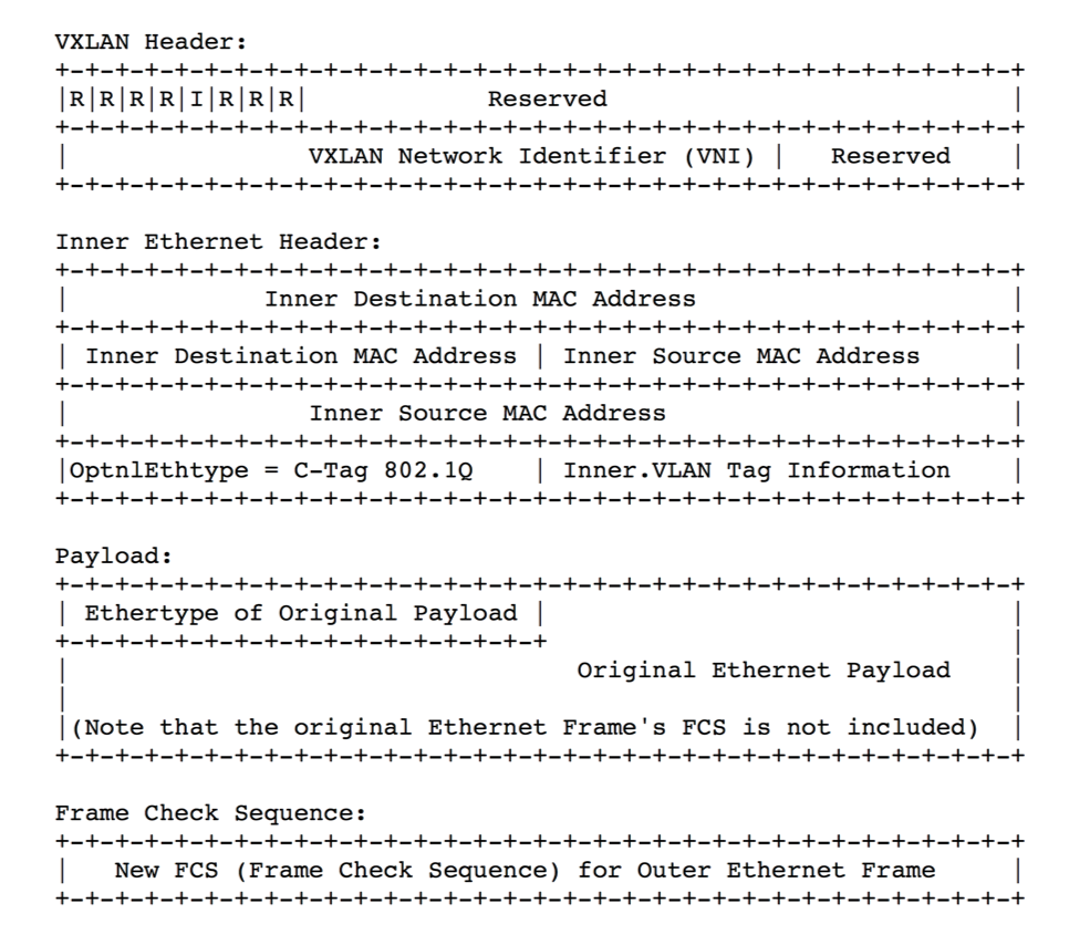
The VXLAN header is shown in Figure 8-1 below.

Figure 8-1: VXLAN Header Added on Top of a Plain UDP Packet (Ethernet + IP + UDP)
VXLAN requires the addition of a variable number of extra octets (i.e., overhead) to all the frames it encapsulates: as shown above, Inner Ethernet Header + Payload + FCS represent the Ethernet frame that originates in the underlay network from a host (virtualized or not). Such original frame is then encapsulated into an 8-octet VXLAN header, which is then encapsulated into a regular UDP (+ IP + 802.3) packet. An outer IEEE 802.1Q VLAN tag is optional and, when present, adds four additional octets to the total.
For example, in case of UDP over IPv4, this equates to a total of 50/54 additional octets of VXLAN encapsulation overhead. In case of UDP over IPv6 an additional 20 octets (compared to IPv4’s case) have to be added due to the longer IPv6 header (for 70/74 bytes of total extra overhead).
About the MTU Configuration
The first obvious implication is that, in order to make sure that variable-length VXLAN encapsulated packets can be successfully carried across a generic Ethernet underlay network, the Maximum Transmission Unit (MTU) size must be properly increased end-to-end on all the physical and logical interfaces connecting the network nodes.
In the IPv4 case the MTU needs to be raised to at least 1554 octets (from the standard 1500 value). In the IPv6 case it needs to be set to at least 1574 octets.
In an Ethernet network, usually this requirement is supported for both cases by enabling jumbo frame forwarding on the device interfaces (at Layer 2 and 3) that have to carry any VXLAN traffic.
About the VXLAN IDs
The second important implication of the VXLAN packet format is that it includes a very useful 24-bit field called VXLAN Network Identifier (VNI). Per the definition in RFC 7348:
VXLAN Segment ID/VXLAN Network Identifier (VNI): this is a 24-bit value used to designate the individual VXLAN overlay network on which the communicating VMs are situated. VMs in different VXLAN overlay networks cannot communicate with each other.
Traditional network segmentation at Layer 2 is implemented with IEEE 802.1Q VLANs to provide logical segmentation of the traffic in different broadcast domains. The use of VLANs, however, imposes a number of limiting factors, especially in large network designs, for example in large multi-tenant data centers.
By leveraging the VNI field as well as a number of VXLAN-based forwarding optimizations it is possible to provide the same Ethernet Layer 2 network services as VLANs but with greater extensibility and flexibility.
In particular, the 24-bit VNI field supports 16 million possible IDs, which is usually considered more than sufficient for the largest network designs.
When compared to VLANs, VNIs offer the following benefits:
- Increased scalability to address more Layer 2 segments as it is possible to map such segments to up to 16 million IDs that can coexist in the same administrative domain.
- Flexible allocation of segment IDs in multi-tenant environments, as it is possible to map each VLAN ID to different unique VNIs (that is, VLAN ID reuse is easily supported). Furthermore, VXLAN’s UDP transport enables the flexible interconnect of data center pods across a generic IP underlay, even when the pods are geographically distributed for redundancy and load sharing purposes.
- Standard routing technologies (Layer 3 forwarding and equal-cost multipath (ECMP) load-balancing) are applied to VNI-based segments in the underlying IP network thanks to VXLAN’s UDP-based encapsulation. This can translate into better network utilization, simpler interoperability in heterogeneous networks and greater scalability enabled by hardware-based forwarding and replication.
About VXLAN’s Layer 2 Extension
The third important implication of the VXLAN packet format is that it can be used to transport Layer 2 traffic from a source to a destination where both source and destination use a single MAC address each (or a limited number of addresses). That is why VXLAN is often likened to a ‘tunnel’ from a source to a destination that carries traffic from any number of end devices.
In more general terms, as we will see in the following, it’s a versatile Layer 3 forwarding path from a source to a destination.
Both source and destination are called VXLAN Tunnel End Points (VTEPs) per the RFC.
One important challenge in today’s virtualized environments is that there is increased demand on MAC address tables of switches that connect to servers. Instead of learning one MAC address per physical server, the switch now has to learn the MAC addresses of the individual VMs, and if the MAC address table overflows, the switch will stop learning new MAC addresses until idle entries age out.
With VXLAN’s end points using a single MAC address, only that address gets exposed to and learned by adjacent transit switches. Therefore, there is no requirement for global learning of all MAC addresses anymore (like in a flat Layer 2 network), and MAC address scalability is only limited by the table size of the switch where the VTEP is configured.
Furthermore, the VNI identifies the scope of the inner MAC frame originated from each host. Therefore, it is possible to utilize overlapping MAC addresses across segments without conflict since, just like with VLANs, the traffic is logically isolated by using different identifiers (the VNIs in case of VXLAN segments).
The aforementioned advantageous implications bring even more benefits to network designers when combined with Pluribus Network’s innovative Adaptive Cloud Fabric and its advanced feature set.
In the following sections we will describe Pluribus’ distinctive implementation of the VXLAN technology, its forwarding optimizations and benefits, as well as its specific configuration steps.
