
Configuring Pluribus Network Packet Broker
Note: The Pluribus Network Packet Broker solution is available on all platforms except NSU, NRU01, NRU02, NRU03, and NRU-S0301 platforms.
The Pluribus Network Packet Broker solution enables users to deploy modular, scale-out, monitoring fabrics with a distributed architecture that allow sharing of visibility and security tools located anywhere in the network. Simple and global monitoring fabrics deployed as part of Network Packet Broker solution feature centralized management capability and hence function as a 'distributed virtual chassis'. Built on top of Netvisor ONE Adaptive Cloud Fabric, Network Packet Broker does not require specialized software or a proprietary fabric, and consequently provides a high degree of flexibility, resiliency, and operational simplicity.
Using network taps or mirrors, the Network Packet Broker service copies traffic from a production network to the ingress ports of the adaptive monitoring fabric. The monitoring fabric, in turn, redirects the traffic arriving on the ingress ports to monitoring tools which can be located geographically apart. This implementation employs VXLAN overlay to transport packets from ingress ports to monitoring tools and features ECMP in the underlay to address link failures.
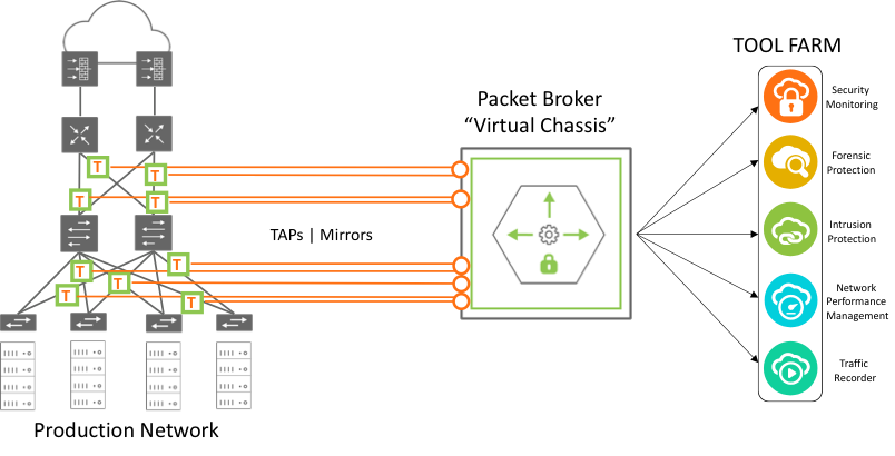
Figure 11-2: Network Packet Broker Architecture
The monitoring fabric can be of any physical topology including leaf-spine, ring, hub-and-spoke, mesh, tree, and others. Netvisor ONE allows you to club the ingress or source ports and the destination ports into Virtual Port Groups (VPGs). The VPG construct permits you to flood the traffic that arrives at select source ports to multiple desired destination ports.
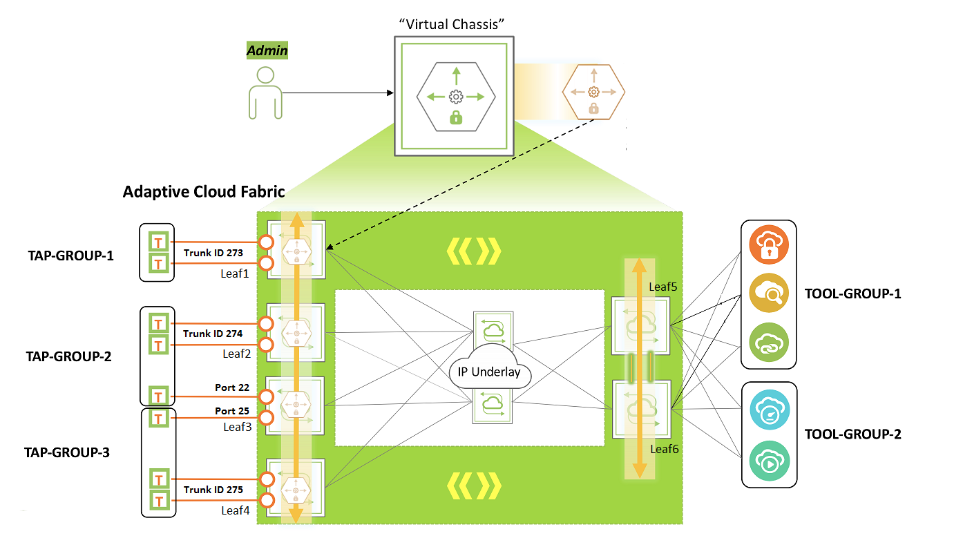
Figure 11-3: Monitoring Fabric Topology
Consider for example, a monitoring fabric with a leaf-spine topology as shown in Figure 10-3. Network taps copy traffic from the production network to the source port or trunk on Leaf1, Leaf2, Leaf3, and Leaf4. These ports constitute the source VPGs: TAP-GROUP-1, TAP-GROUP-2, and TAP-GROUP3. The switches Leaf5 and Leaf6 form a cluster. The monitoring tools are connected to ports on Leaf5 and Leaf6 which constitute the destination VPGs: TOOL-GROUP-1 and TOOL-GROUP-2. This topic describes the steps to configure VPGs and create a forwarding policy.
Before creating the VPGs, you must configure a VXLAN underlay network and VTEPs for the overlay. For details, refer to the sections, 'Configuring the VXLAN Underlay Network' and 'Configuring the Overlay: VTEP Interconnections and VNIs'.
Also, to deploy the Packet Broker fabric that spreads across geographical locations, you must create a Fabric over Layer 3 configuration. For details, refer to the section, 'Configuring a Fabric over a Layer 3 Network'.
Follow the steps below to configure the port groups and to send traffic from a source port group to a destination port group:
1. Configuring Source VPGs
Create VPGs for the source ports of the monitoring fabric, by using the command vpg-create.
CLI (network-admin@switch1) > vpg-create
|
vpg-create |
Creates a Virtual Port Group (VPG) |
|
vnet vnet-name |
Specify the name of the vNET. |
|
name name-string |
Specify the name of the VPG. |
|
type source|destination|bidirectional |
Specify the type of the VPG as source, destination, or bidirectional. |
|
ports port-list |
Specify the ports assigned to the VPG. |
CLI (network-admin@Leaf1) > vpg-create vnet vnet1 name TAP-GROUP-1 type source
CLI (network-admin@Leaf1) > vpg-create vnet vnet1 name TAP-GROUP-2 type source
CLI (network-admin@Leaf1) > vpg-create vnet vnet1 name TAP-GROUP-3 type source
Netvisor ONE version 6.1.0 adds the vnet parameter to vpg-create and vpg-show commands. This feature enables you to configure or manage the NPB solution fabric-wide over vNET managed ports. This feature also helps you to get a segregated view of the NPB solution and supports multi-tenancy.
Netvisor ONE 6.1.0 release also introduces support for bidirectional VPGs. For more information, refer to the topic Configuring Protocol Transparency and Bidirectional VPGs for NPB.
Add the source ports to the VPGs by using the vpg-port-add command:
CLI (network-admin@Leaf1) > vpg-port-add
|
vpg-port-add |
Adds ports to a VPG. |
|
vpg-name name-string |
Specify the name of the VPG. |
|
ports port-list |
Specify the ports assigned to the VPG. |
The switches Leaf1, Leaf2, and Leaf3 form trunks (Link Aggregation Groups) with network taps, with trunk IDs 273, 274, and 275 as shown in Figure 10-2.
CLI (network-admin@Leaf1) > vpg-port-add vpg-name TAP-GROUP-1 ports 273
CLI (network-admin@Leaf2) > vpg-port-add vpg-name TAP-GROUP-2 ports 274
CLI (network-admin@Leaf3) > vpg-port-add vpg-name TAP-GROUP-2 ports 22
CLI (network-admin@Leaf3) > vpg-port-add vpg-name TAP-GROUP-3 ports 25
CLI (network-admin@Leaf4) > vpg-port-add vpg-name TAP-GROUP-3 ports 275
Note: The source VPG can include ports from all the nodes in the fabric. However, this port group can only include at most one port or trunk from each node.
To view the VPG configuration, use the command vpg-show.
CLI (network-admin@Leaf1) > vpg-show
|
vpg-show |
Displays VPG configuration details. |
|
scope |
The scope of the VPG. |
|
vnet vnet-name |
The name of the vNET. |
|
name name-string |
The name of the VPG. |
|
type source|destination |
The type of VPG. |
|
ports port-list |
The ports assigned to the VPG. |
|
vni 0..16777215 |
The VNI for VXLAN. |
|
vlan 0..4095 |
The VLAN ID. |
CLI (network-admin@leaf1) > vpg-show
switch scope vnet name type ports vni vlan
------ ------ ----- ----------- ------ ----- --- ----
Leaf1 fabric vnet1 TAP-GROUP-3 source none 0 0
Leaf2 fabric vnet1 TAP-GROUP-3 source 25 0 0
Leaf3 fabric vnet1 TAP-GROUP-3 source 275 0 0
Leaf4 fabric vnet1 TAP-GROUP-3 source none 0 0
Leaf5 fabric vnet1 TAP-GROUP-3 source none 0 0
Leaf6 fabric vnet1 TAP-GROUP-3 source none 0 0
Spine1 fabric vnet1 TAP-GROUP-3 source none 0 0
Spine2 fabric vnet1 TAP-GROUP-3 source none 0 0
Leaf1 fabric vnet1 TAP-GROUP-2 source none 0 0
Leaf2 fabric vnet1 TAP-GROUP-2 source 274 0 0
Leaf3 fabric vnet1 TAP-GROUP-2 source 22 0 0
Leaf4 fabric vnet1 TAP-GROUP-2 source none 0 0
Leaf5 fabric vnet1 TAP-GROUP-2 source none 0 0
Leaf6 fabric vnet1 TAP-GROUP-2 source none 0 0
Spine1 fabric vnet1 TAP-GROUP-2 source none 0 0
Spine2 fabric vnet1 TAP-GROUP-2 source none 0 0
Leaf1 fabric vnet1 TAP-GROUP-1 source 273 0 0
Leaf2 fabric vnet1 TAP-GROUP-1 source none 0 0
Leaf3 fabric vnet1 TAP-GROUP-1 source none 0 0
Leaf4 fabric vnet1 TAP-GROUP-1 source none 0 0
Leaf5 fabric vnet1 TAP-GROUP-1 source none 0 0
Leaf6 fabric vnet1 TAP-GROUP-1 source none 0 0
Spine1 fabric vnet1 TAP-GROUP-1 source none 0 0
Spine2 fabric vnet1 TAP-GROUP-1 source none 0 0
2. Configuring Destination VPGs
Create destination tool groups by using the following commands:
CLI (network-admin@Leaf5) > vpg-create vnet vnet1 name TOOL-GROUP-1 type destination
CLI (network-admin@Leaf5) > vpg-create vnet vnet1 name TOOL-GROUP-2 type destination
Note: For destination VPG creation to be successful, you must add at least one port to the vxlan-loopback-trunk on all the nodes of the NPB fabric, including spine switches. For more details, refer to Configuring the VXLAN Loopback Trunk topic of the Configuring VXLAN chapter.
Add the ports connected to the monitoring tools into the tool groups by using the command vpg-port-add:
For example:
CLI (network-admin@Leaf5) > vpg-port-add vpg-name TOOL-GROUP-1 ports 22,34,45
CLI (network-admin@Leaf6) > vpg-port-add vpg-name TOOL-GROUP-1 ports 47,50
CLI (network-admin@Leaf5) > vpg-port-add vpg-name TOOL-GROUP-2 ports 17,32
CLI (network-admin@Leaf6) > vpg-port-add vpg-name TOOL-GROUP-2 ports 48,55
The vpg-port-add commands auto-create bridge domains for TOOL-GROUP1 and TOOL-GROUP-2. These bridge domains flood the arriving traffic to the ports in the respective tool groups.
Use the vpg-show command to view the configuration:
CLI (network-admin@leaf1) > vpg-show type destination
switch scope vnet name type ports vni vlan
------ ------ ----- ------------ ----------- ----- -------- ----
Leaf1 fabric vnet1 TOOL-GROUP-2 destination none 12666666 2833
Leaf2 fabric vnet1 TOOL-GROUP-2 destination none 12666666 2833
Leaf3 fabric vnet1 TOOL-GROUP-2 destination none 12666666 2833
Leaf4 fabric vnet1 TOOL-GROUP-2 destination none 12666666 2833
Leaf5 fabric vnet1 TOOL-GROUP-2 destination 17,32 12666666 2833
Leaf6 fabric vnet1 TOOL-GROUP-2 destination 48,55 12666666 2833
Spine1 fabric vnet1 TOOL-GROUP-2 destination none 12666666 2833
Spine2 fabric vnet1 TOOL-GROUP-2 destination none 12666666 2833
Leaf1 fabric vnet1 TOOL-GROUP-1 destination none 12000000 2500
Leaf2 fabric vnet1 TOOL-GROUP-1 destination none 12000000 2500
Leaf3 fabric vnet1 TOOL-GROUP-1 destination none 12000000 2500
Leaf4 fabric vnet1 TOOL-GROUP-1 destination none 12000000 2500
Leaf5 fabric vnet1 TOOL-GROUP-1 destination 22,34,45 12000000 2500
Leaf6 fabric vnet1 TOOL-GROUP-1 destination 47,70 12000000 2500
Spine1 fabric vnet1 TOOL-GROUP-1 destination none 12000000 2500
Spine2 fabric vnet1 TOOL-GROUP-1 destination none 12000000 2500
Note: Netvisor ONE auto-generates a VNI and reserved VLAN ID for the destination VPGs.
3. Configuring the vFlow Policy
As the final step of the configuration, create a vFlow to forward traffic from the desired source port group to a destination port group. For example, use the following command to send SSH traffic from TAP-GROUP-1 to TOOL-GROUP-2:
CLI (network-admin@switch1) > vflow-create name TAP1-TOOL2 scope fabric proto tcp src-vpg TAP-GROUP-1 dst-vpg TOOL-GROUP-2
This configuration floods the ingress traffic matching the vFlow to all the ports in TOOL-GROUP-2 over the VXLAN tunnel.
Netvisor ONE version 6.1.0 supports the configuration of a vFlow action along with traffic redirection from a source VPG to a destination VPG, using a single command. In earlier versions of Netvisor ONE, this required two separate vFlow commands: one for configuring source and destination VPGs and one for configuring the action.
For example, with the current release, you can configure an action of setvlan to assign a VLAN to all the packets that are copied between the source and destination VPGs:
CLI (network-admin@switch1) > vflow-create name TAP1-TOOL2 scope fabric proto tcp src-vpg TAP-GROUP-1 dst-vpg TOOL-GROUP-2 action setvlan action-value 20
The command above assigns VLAN 20 to the copied packets.
Note: The running configuration for the vflow-create command has parameters such as in-port and action-set-svp-value. However, while configuring a vFlow, you should not supply these parameters as these fields are auto-populated.
Additional CLI Commands
1. vpg-delete
Use this command to delete a VPG. You cannot delete a VPG that is associated with a vFlow. In such cases, you must delete the vFlow before you delete the VPG.
CLI (network-admin@Leaf1) > vpg-delete
|
vpg-delete |
Deletes a VPG. |
|
name name-string |
Specify the name of the VPG. |
For example:
CLI (network-admin@Leaf1) > vpg-delete name <vpg-name>
2. vpg-port-remove
Use this command to remove ports from a VPG.
CLI (network-admin@Leaf1) > vpg-port-remove
|
vpg-port-remove |
Removes ports from a VPG. |
|
vpg-name name-string |
Specify the name of the VPG. |
|
ports port-list |
Specify the ports to be removed from the VPG. |
For example:
CLI (network-admin@Leaf1) > vpg-port-remove vpg-name <vpg-name> ports <port-list>
Note: For a given switch, if you remove a port or trunk from a source VPG, the associated vFlow on that switch is disabled in hardware but it is retained by the software.