
Configuring Distributed VRF-aware vFlow
Netvisor ONE version 6.0.0 introduces Virtual Routing and Forwarding (VRF) -aware vFlows, which enables vFlows to operate at scale in a distributed VRF environment. This feature extends support for Policy Based Routing (PBR) in a VRF. By using the VRF-aware vFlow enhancement, you can implement L3 or L4 security access lists, micro-segmentation, QoS, and monitoring features in a fabric with distributed VRFs.
Configuring Distributed VRF-aware Policy Based Routing
Distributed PBR enables service insertion (adding services into the forwarding path of traffic) of constructs such as firewalls. When a firewall is inserted into a network, the traffic originating from a VRF instance needs to be redirected to the firewall or DC gateway through a next-hop address or an ECMP group.
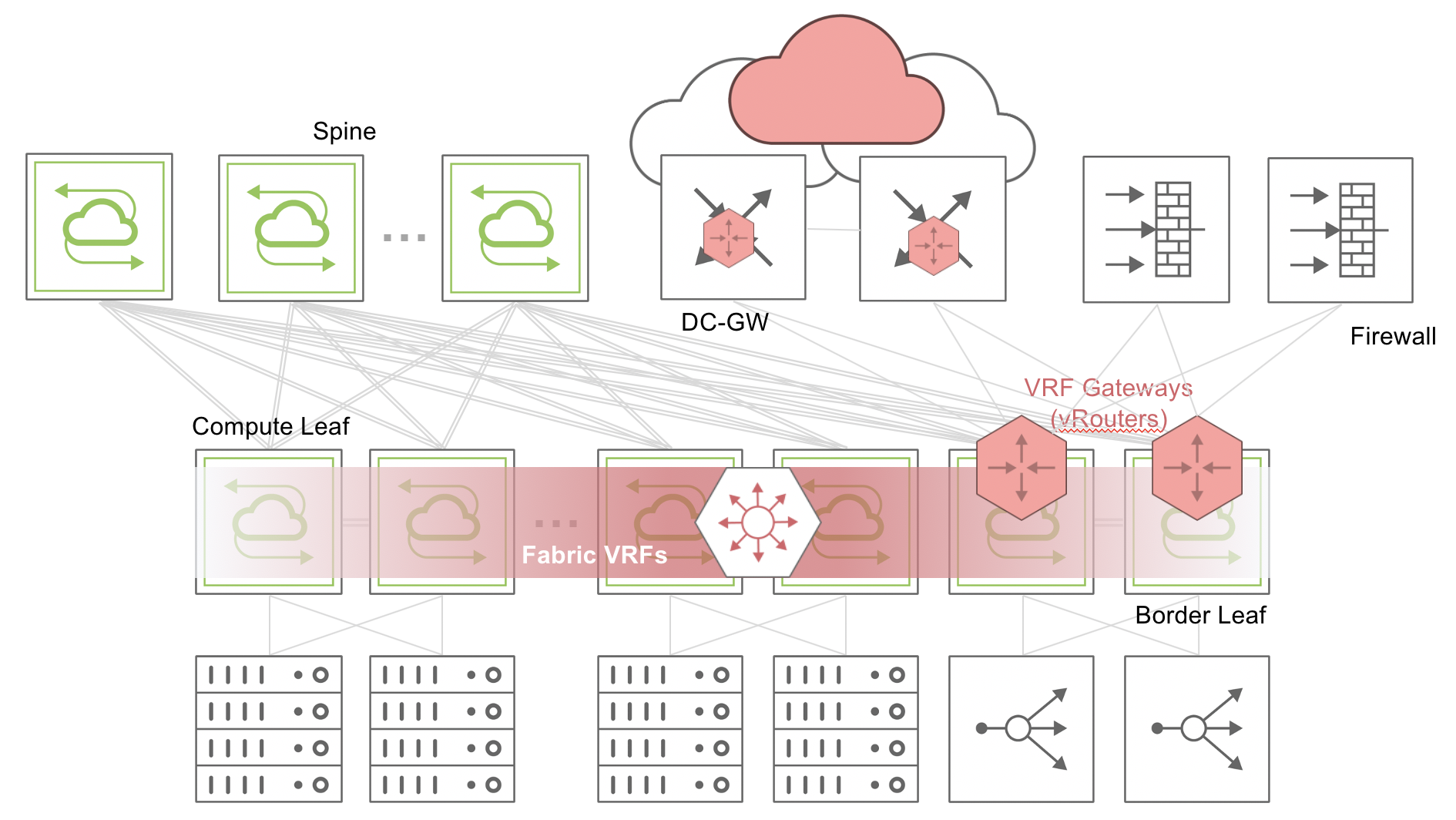
Figure 8-17 - Distributed VRF-aware Policy-based Routing
For instance, in a spine-leaf topology as shown in Figure 8-17, if traffic with a source IP address of 100.1.1.10 in a VRF needs service insertion of a firewall, you can create a vFlow to redirect the traffic to a next hop address or ECMP group. When the traffic matches the source IP address of 100.1.1.10, traffic is sent to the next hop or ECMP group indicated in the vFlow, instead of being forwarded based on the Layer 3 routing entries.
You must enable PBR globally to create vFlows . You can enable PBR by using the command:
CLI (network-admin@switch1) > system-settings-modify policy-based-routing
Note: nvOSd must be restarted for this setting to take effect
Now, create a vFlow to send the packets from the source IP address to the required next hop IP address by using the command:
CLI (network-admin@switch1) > vflow-create name flow1 scope local vrf vrf-1 src-ip 100.1.1.10 action to-next-hop-ip action-to-next-hop-ip-value 150.1.1.2
To view the details of the vFlow, use the command vflow-show:
CLI (network-admin@switch1) > vflow-show layout vertical
name: flow1
scope: local
type: pbr
src-ip: 100.1.1.10
vrf: vrf-1
burst-size: auto
precedence: default
action: to-next-hop-ip
action-to-ecmp-group-value: 150.1.1.2
enable: enable
table-name: System-L3-L4-PBR-1-0
If there are multiple plausible next hop IP addresses to reach a firewall, you can perform load balancing by creating a static ECMP group and adding the next hop addresses (up to 16) to the ECMP group. Then, configure a vFlow to send the required traffic to the ECMP group and in turn, to the firewall. For details regarding configuration of ECMP groups, refer to the Sending Network Traffic to an ECMP Group with PBR section.
For example, to create a vFlow to send packets to a pre-configured ECMP group named vrf_ecmp (previously created with the static-ecmp-group-create command), use the vflow-create command with the action keyword to-ecmp-group:
CLI (network-admin@switch1) > vflow-create name flow2 scope local in-port 23 src-ip 10.0.11.100 src-ip-mask 255.255.255.0 dst-ip 10.0.12.100 dst-ip-mask 255.255.255.0 vrf vrf-2 action to-ecmp-group action-to-ecmp-group-value vrf_ecmp
To view the configuration details, use the vflow-show command:
CLI (network-admin@switch1) > vflow-show
name: flow2
scope: local
type: pbr
in-port: 23
src-ip: 10.0.11.100/255.255.255.0
dst-ip: 10.0.12.100/255.255.255.0
vrf: vrf-2
burst-size: auto
precedence: default
action: to-ecmp-group
action-to-ecmp-group-value: vrf_ecmp
enable: enable
table-name: System-L3-L4-PBR-1-0
Configuring Distributed VRF-aware Security Access Lists
Netvisor ONE supports L3 and L4 security access lists for traffic in a VRF. The keywords drop or none can be supplied to the action parameter in the vflow-create command, to drop or allow packets.
For example, to drop all packets from the source IP address 100.1.1.10 in a VRF, use the command:
CLI (network-admin@switch1) > vflow-create name flow10 scope local src-ip 100.1.1.10 vrf vrf5 action drop
To view the vFlow details, use the command vflow-show:
CLI (network-admin@switch1) > vflow-show layout vertical
name: flow10
scope: local
type: pbr
src-ip: 100.1.1.10
dst-ip: none
vrf: vrf5
burst-size: auto
precedence: default
action: drop
action-value: none
metadata: none
enable: enable
table-name: System-L3-L4-PBR-1-0
Configuring Distributed VRF-aware Micro-segmentation
Micro-segmentation is the process of creating secure zones within a fabric to isolate workloads. The distributed VRF-aware vFlow feature allows you to create security zones in a fabric. You can configure micro-segmentation by creating L3 or L4 filters for internal tagging during ingress and making an aggregated egress decision.
For example, define a security zone (A) in a VRF. The zones can be based on various source IP address criteria, such as, across subnets, external subnets, and intra-subnet.
Create vFlows that define zone A as the source:
CLI (network-admin@switch1) > vflow-create name ZONE-A-SOURCE-10.1 scope fabric vrf VRF-1 src-ip 10.10.1.0/24 action set-metadata action-value 10 precedence 5
CLI (network-admin@switch1) > vflow-create name ZONE-A-SOURCE-10.1 scope fabric vrf VRF-1 src-ip 10.10.128.0/20 action set-metadata action-value 10 precedence 5
CLI (network-admin@switch1) > vflow-create name ZONE-A-SOURCE-10.3 scope fabric vrf VRF-1 src-ip 10.10.33.0/24 action set-metadata action-value 10 precedence 5
CLI (network-admin@switch1) > vflow-create name ZONE-A-SOURCE-10.4 scope fabric vrf VRF-1 src-ip 10.10.64.0/20 action set-metadata action-value 10 precedence 5
Create vFlows that define zone A as the destination. These vFlows are given a lower precedence in this example.
CLI (network-admin@switch1) > vflow-create name ZONE-A-DESTIN-11.1 scope fabric vrf VRF-1 dst-ip 10.10.1.0/24 action set-metadata action-value 11 precedence 3
CLI (network-admin@switch1) > vflow-create name ZONE-A-DESTIN-11.1 scope fabric vrf VRF-1 dst-ip 10.10.128.0/20 action set-metadata action-value 11 precedence 3
CLI (network-admin@switch1) > vflow-create name ZONE-A-DESTIN-11.3 scope fabric vrf VRF-1 dst-ip 10.10.33.0/24 action set-metadata action-value 11 precedence 3
CLI (network-admin@switch1) > vflow-create name ZONE-A-DESTIN-11.4 scope fabric vrf VRF-1 dst-ip 10.10.64.0/20 action set-metadata action-value 11 precedence 3
Zone A uses metadata 10 for traffic that leaves specific IP addresses and metadata 11 for traffic that arrives at specific IP addresses. Now, you can create egress micro-segmentation rules based on the security zone. The metadata values are among the parameters that define the egress policies, and these values help in making the egress decision to send the packets out.The egress policies are defined in Egress-Table-1-0 or the Egress Content Aware Processing (ECAP) hardware filter table.
For example, to allow UDP traffic from zone A to the destination IP address 172.10.0.0/8, use the following command:
CLI (network-admin@switch1) > vflow-create name ZONE-A-172.10-UDP-PASS table-name Egress-Table-1-0 vrf VRF-1 metadata 10 dst-ip 172.10.0.0/8 proto 17 action none
To allow TCP traffic from zone A to the destination IP address 172.10.0.0/8 and the reverse, use the set of following commands:
CLI (network-admin@switch1) > vflow-create name ZONE-A-172.10-TCP-PASS table-name Egress-Table-1-0 vrf VRF-1 metadata 10 dst-ip 172.10.0.0/8 proto 6 action none
CLI (network-admin@switch1) > vflow-create name 172.10-ZONE-A-TCP-PASS table-name Egress-Table-1-0 vrf VRF-1 metadata 11 src-ip 172.10.0.0/8 proto 6 action none
Configuring Distributed VRF-aware QoS Policies
You can use vFlows to set Differentiated Services Code Point (DSCP) and VLAN priority values for traffic in a VRF. For example, to set a DSCP value of 10 for traffic originating from 10.10.1.0/24, use the command:
CLI (network-admin@switch1) > vflow-create name flow5 scope local vrf VRF_2 src-ip 10.10.1.0 action set-dscp action-value 10
To view the details, use the vflow-show command:
CLI (network-admin@switch1) > vflow-show layout vertical
name: flow5
scope: local
type: pbr
src-ip: 10.10.1.0
dst-ip: none
vrf: vrf_2
burst-size: auto
precedence: 10
action: set-dscp
action-value: 10
metadata: none
enable: enable
table-name: System-L3-L4-PBR-1-0
To set a VLAN priority value of 5 for traffic from 10.10.1.1/24, use the command:
CLI (network-admin@switch1) > vflow-create name flow6 scope fabric vrf VRF_3 src-ip 10.10.1.1/24 action set-vlan-pri action-value 5
Configuring Distributed VRF-aware vFlow-based Monitoring
You can copy packets to a port or CPU for traffic monitoring by using the action keywords copy-to-cpu and copy-to-port.
For example, to copy the packets with the source IP address of 10.1.1.1 in vrf10 to the CPU, use the command:
CLI (network-admin@switch1) > vflow-create name flow5 scope local vrf vrf10 src-ip 10.1.1.1 action copy-to-cpu
Use the vflow-show command to view the details:
CLI (network-admin@switch1) > vflow-show layout vertical
name: flow5
scope: local
type: pbr
src-ip: 10.1.1.1
vrf: vrf10
burst-size: auto
precedence: default
action: copy-to-cpu
action-value: none
enable: enable
table-name: System-L3-L4-PBR-1-0
To copy packets with a source IP 10.1.1.2 in vrf10 to port 25, use the command:
CLI (network-admin@switch1) > vflow-create name flow7 scope local vrf vrf10 src-ip 10.1.1.2 action copy-to-port action-to-ports-value 25
For details on vFlows, see the Configuring and Using vFlows chapter.