
Understanding Virtual Link Extension (vLE)
Pluribus Networks offers a highly flexible approach to software-defined networking (SDN), called Unified Cloud Fabric, which leverages a sophisticated distributed architecture in order to enable organizations to build scalable private and public clouds with the very desirable benefits of ease of management, reliability, security and performance.
With regard to ease of management and flexibility, the VXLAN technology described in the Understanding VXLAN chapter augments the Unified Cloud Fabric with a plethora of advanced capabilities. Among such features is the ability to natively transport traffic across the VXLAN fabric for end-to-end data center connectivity through overlay bridging and distributed routing.
Furthermore, in certain scenarios, network administrators have the requirement for the VXLAN fabric to be able to transport traffic transparently between two different ports as if interconnected through a virtual pipe: in other words, what comes in on one end goes out of the other end. This capability is often referred to as a ‘pseudo-wire’ in the literature. Pluribus calls it a virtual wire.
Pluribus Virtual Link Extension (vLE) implements a transparent point-to-point virtual link over the VXLAN fabric to emulate the connectivity of an actual wire interconnecting any two fabric ports selected by the user, as shown in Figure 9-1 below.
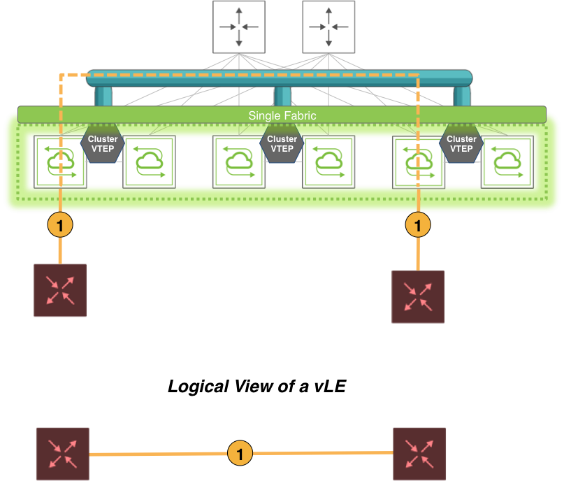
Figure 9-1: Virtual Link Extension over the VXLAN Fabric
The key characteristic of a vLE is its ability to take what comes in on the local end of the virtual pipe and send it to the remote end. That includes regular data plane traffic as well as Layer 2 PDUs.
Hence, one application of Pluribus’ Virtual Link Extension feature is the remote monitoring of traffic between two fabric ports.
Another common use case is lab automation, i.e., the flexible interconnection of lab equipment through the fabric: with multiple vLEs the port interconnections can be dynamically (for example, programmatically) managed by the lab administrator through the creation of ad-hoc virtual pipes.
This type of use case is sometimes also referred to as 'IP Virtual Wire' (as it runs on top of a VXLAN overlay) or 'Virtual Wire+' to distinguish it from the regular (Layer 1) VirtualWire™ functionality (refer to the Configuring VirtualWire Deployment Guide). It is usually deployed with error transparency enabled (see below for more details).
From an implementation perspective, it should be noted that the Unified Cloud Fabric can transport multiple vLEs across a common high-performance VXLAN-based interconnect, thus enabling a very high degree of configuration flexibility and scalability. The main network constraint is the maximum bandwidth available on any of the shared physical links, which however can be scaled using higher speed Ethernet ports or trunks to avoid any chokepoints.
From a network design standpoint, in terms of ease of configuration, vLEs can use manual or automatic VXLAN tunnels to piggyback the mirrored traffic end-to-end and thus they enjoy the same wide-spanning benefits of any other VXLAN-based feature. The only constraint is that they cannot share the same VXLAN tunnels with other features.
Alternatively, the Pluribus UNUM™ management platform can be leveraged to very effectively perform the provisioning of the entire vLE deployment in very few steps. First, a Layer 3 fabric can be deployed from a UNUM Layer-3 Playbook. Then, Manager --> Services --> Manage vLE can be used to create and manage one or more vLEs through user-friendly configuration forms. (Refer to the UNUM Fabric Manager documentation for more details.)
Finally, programmatic creation and management of vLEs can be performed through REST APIs.
About Virtual Link Extension State Tracking
Just as in the case of physical back-to-back Ethernet connections, it is usually desirable that if one end of a vLE goes down the peer end mirrors that state change.
This behavior is called link state tracking. With such symmetric behavior, link state changes can be propagated end-to-end and hence network nodes or endpoints are able to react to them.
In other words, when a vLE is created with tracking enabled between two physical ports of two switches, the vLE remains up as long as both physical ports are in the link up state.
When a vLE is created with tracking enabled between two trunk ports (a.k.a. port channels), the vLE stays up as long as at least one member port in the trunk is up and the remote trunk is also up. When the last trunk member goes down, the vLE is brought down. (Note that when you configure vLE tracking on a trunk port, you cannot configure tracking on individual trunk members.)
In the CLI link state tracking can be enabled/disabled over each vLE individually through the tracking|no tracking option. (In fact, having tracking enabled may not be required in all cases, such as for troubleshooting purposes.) Similarly, in the Pluribus UNUM management platform the tracking|no tracking option corresponds to a true/false configuration checkbox to be ticked by the user.
For more CLI configuration details refer to the Configuring Virtual Link Extension State Tracking section below. Refer to the UNUM Fabric Manager documentation for the specific pane and dashboard layout details for the link state tracking configuration checkbox.
The node-1-port and node-2-port are the names of the two vLE endpoints whose link state can be tracked. When node-1-port goes down the vle-show command can be used to check and display the overall vLE state, which is local-down. When node-2-port goes down, instead, the vle-show command displays the remote-down state.
If needed, as part of the vLE configuration, it is also possible to tweak the timing to be used by the tracking logic to detect a port down state and to trigger a (virtual) link down event.
For more details refer to the following sections.
About Virtual Link Extension Between Two Ports of the Same Switch
In earlier versions of Netvisor ONE, the vLE implementation supported only one vLE endpoint per node. With version 5.1.1, both vLE endpoints can be part of the same node. This configuration is referred to as local vLE.
A vLE can have two ports in the same node only if the corresponding vLE’s VXLAN ID is not already mapped to a tunnel. Similarly, a tunnel can be mapped to a vLE’s VXLAN ID if there is at most one local port in the vLE. In the case of auto-tunnels, a VXLAN ID can be mapped to a VTEP only if there is at most one local port in the node associated with that VTEP.
Netvisor ONE allows the users to track the vLE port status when part of a local vLE. In such case, the node-1 and node-2 labels refer to the same switch. However, for consistency reasons, the node-2-port is still considered as ‘remote port’ in the vle-show output, even though in actuality both the vLE ports are on the same switch.
Let us assume, for example, that port 30 (node-2-port) goes down, the vLE status is displayed as remote-down (see example below) so the user can understand exactly which port is causing the vLE to be down. Instead, if port 22 (node-1-port) is down, then the vLE status is displayed as local-down.
CLI (network-admin@switch) > vle-show layout vertical
name: vle1
vnet:
node-1: vanquish1
node-2: vanquish1
node-1-port: 22
node-2-port: 30
status: remote-down
tracking: enabled
ports-state: override
create-time: 09:44:56
Use the port-show command to check if the node-2-port status is down or vle-wait. The vle-wait state indicates that the port is brought down due to remote port being down
About Virtual Link Extension Redundancy with Clusters
In network designs using pseudo-wires, link redundancy can be achieved by creating trunks using (at least) pairs of pseudo-wires as shown below. Such trunks originate and terminate on the end devices.
That can be conveniently achieved in fabric designs that leverage pairs of leaf switches (called clusters in Pluribus parlance) to provide redundancy for Layer 2 and Layer 3 last-hop traffic: as shown in Figure 9-2 below, when vLEs are configured, vLE redundancy can be implemented by setting up one vLE per cluster switch and by leveraging port channeling or NIC teaming (depicted with an ellipse in the diagram) on the end devices to implement end-to-end vLE trunks.
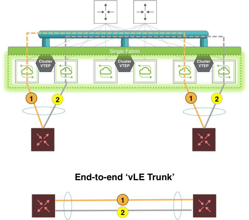
Figure 9-2: Virtual Link Extension End-to-end Redundancy
Leaf switches don’t need to implement load balancing and failover for the vLE trunks as vLEs are in essence just end-to-end transparent pipes, which transport all the traffic and propagate port state changes through link state tracking. Hence, vLE-attached end devices can just use standard 802.3ad link bundling, static or dynamic with the LACP protocol, to manage the aggregation and the failover of the virtual wires.
vLE redundancy has the following characteristics:
- Failover between VTEPs used by vLEs is not required.
- Hence VTEPs associated with vLEs do not use a VRRP virtual IP address. They use a primary IP address, instead, or the real IP address of a dedicated interface.
- L2 PDUs such as LACP messages on vLE transparent VLANs are not sent to a fabric node’s management CPU, as they need to be passed transparently through the virtual wire.
In the example topology shown above in Figure 9-2, two generic switches are connected respectively to two cluster leaf nodes. There is no vLAG on such nodes as it is not required. Both generic switches are configured with the LACP protocol on their trunk links to run connectivity checks and to form the trunk dynamically. Hence, they are directly in charge of link redundancy and failover management, whereas the leaf nodes are responsible for transparent end-to-end traffic transport.
About Virtual Link Extension Error Transparency
In lab automation deployments employing vLE it is usually required to not only transport valid data plane frames and PDUs but also to include potential malformed frames that are received on a vLE port.
Starting from Netvisor ONE release 5.1.1, with the optional configuration for error transparency, a vLE can be configured to transport also bad CRC frames as well as runts (i.e., undersized frames). Transported runt frames are padded with zeros up to a length of 64 bytes and their CRC is zeroed out, which can be used to recognize an undersized frame on the receiving end.
Error transparency is hardware-dependent (on newer ASICs) and thus works only on the following capable platforms:
- Dell S4100 Series
- Dell S5048
- Dell S5200 Series
- Dell Z9100
- Freedom F9372-X and F9372-T
In particular, on these platforms undersized frames with a minimum length of 50 bytes are supported.
Furthermore, full jumbo frame transport is also supported in Netvisor ONE version 5.1.1 by upping the maximum supported MTU size to 9398 bytes.
Refer to the Enabling Jumbo Frame Support section of this Configuration Guides for command details.
Error transparency is enabled globally to minimize the configuration steps required in lab automation setups. However, since it disables CRC checks even on inter-switch links, it can be turned off on a per port basis wherever it’s not required.
About Virtual Link Extension Traffic Analytics
Netvisor ONE does not make copies of vLE-transported control frames (such as LLDP, etc.) to the switch management CPU. Any inner VLAN tag, if present, is also preserved. This is achieved by installing a system vFlow entry called Virtual-Link-Extend with the highest priority of 15 with no action specified so that control frames are not terminated and sent to CPU.
In addition, to support vLE traffic analytics, a few additional system vFlow entries (named System-vLE-x, where x can be S or F or R) are installed with the same priority as the Virtual-Link-Extend entry in order to copy TCP SYN/FIN/RST packets to the management CPU. This ensures that any SYN/FIN/RST packets carried by vLE can be used for TCP flow analysis.
The vflow-system-show command can be used to display such system entries used for transparency and flow analysis:
CLI (network-admin@switch) > switch * vflow-system-show name Virtual-Link-Extend
switch name scope type precedence action enable table-name
------- ------------------- ----- ------ ---------- ------ ------ --------------------
switch Virtual-Link-Extend local system 15 none enable System-L1-L4-Tun-1-0
switch1 Virtual-Link-Extend local system 15 none enable System-L1-L4-Tun-1-0
switch2 Virtual-Link-Extend local system 15 none enable System-L1-L4-Tun-1-0
CLI (network-admin@switch) > connection-show layout vertical
vnet: 100
vlan: 100
vxlan: 10100
src-ip: 20.20.20.1
dst-ip: 20.20.20.2
dst-port: http
cur-state: fin
syn-resends: 0
syn-ack-resends: 0
latency: 74.8us
obytes: 149
ibytes: 311
total-bytes: 460
age: 2h11m21s