
Understanding vLAGs
The virtual chassis logical model can be effectively used to enable an advanced capability called multi-chassis link bundling/port channeling. This feature is also referred to as MC-LAG (Multi-Chassis Link Aggregation Group).
An MC-LAG is a cross-device link bundle (i.e., trunk). It typically has at least one port member on one switch and another port member on a backup switch. It can be facing downstream toward an end point (configured with a regular LAG on its end) or upstream toward another switch or router (also using a regular LAG or even an MC-LAG).
The IEEE 802.1AX-2008 standard for link aggregation (LAG) does not mention MC-LAG but does not preclude it, because the implementation of the required synchronization technology can be vendor-specific without affecting interoperability. Such additional under the hood (i.e., mostly transparent) synchronization technology performs advanced functions such as automatic MAC address learning synchronization across members, sharing of the same switch MAC and STP system ID, sharing of port state and information even during dynamic protocol negotiations, etc.
Pluribus’ implementation of MCLAG is called vLAG (Virtual Link Aggregation Group) on a switch cluster. That in practice means that in order to be able to configure a vLAG a cluster pair needs to be set up first.
As mentioned in an earlier section, a necessary requirement for a cluster to be created is to provision a redundant horizontal connection between the two cluster members: in Pluribus parlance this process is called automatic LAG (link aggregation) of the intra-cluster trunk. As long as at least two ports on both cluster members are physically interconnected, the automatic LAG logic will take care of bundling them together and provisioning them as intra-cluster trunk.
The cluster trunk is just a regular LAG, but is the pivot around which various important functions revolve. First off, it provides a critical communication channel utilized for cluster synchronization activities as well as protocol exchanges. It is also instrumental for supporting the MC-LAG (a.k.a. vLAG) function on the cluster, as it can function as a backup forwarding path during failover scenarios. (Therefore it must be a fat enough data pipe to prevent potential bottlenecks in case of failures.)
From a high level point of view, a vLAG is a single logical but physically redundant upstream or downstream connection across a pair of cluster switches (see also Figure 4 below). In other words, physically it’s a triangular topology that includes the cluster trunk, while logically it appears just as if it were a point-to-point multi-link connection.
This property makes active-active vLAGs ideal for a number of Layer 2 or Layer 3 network designs, where standard port bundling/port channeling technologies (IEEE 802.3ad) can be used for high availability and very fast traffic steering (due to multi-pathing) in case of link failure. (See also the examples in the figures below.)
Using clusters with vLAGs for instance is a technique often chosen to avoid using the Spanning Tree Protocol (STP) for Layer 2 redundancy.
Figure 7-4 below shows how a vLAG is used to present a router/switch with a single logical connection instead of two separate ones. Therefore, in case of a Layer 2 configuration, loop prevention is not needed on that network segment (as no loop is present).
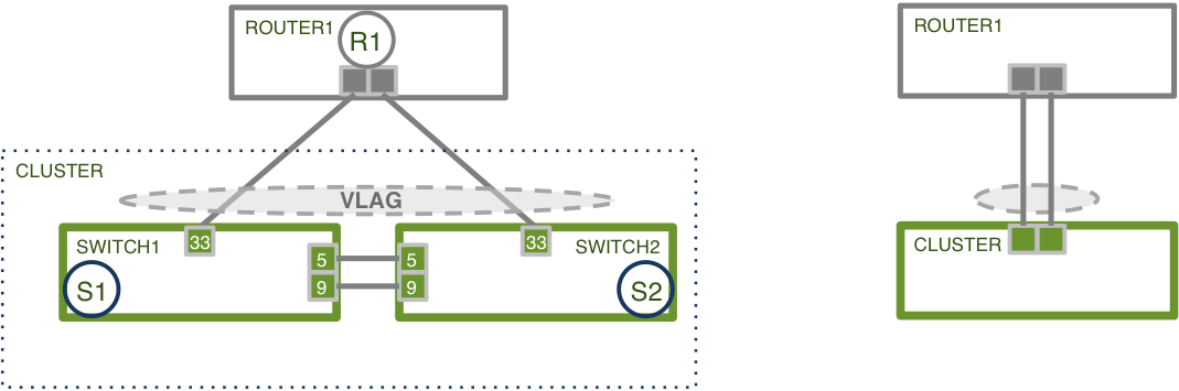
Figure 7-4 - Logical View of a vLAG from an External Device
Furthermore, the same strategy can be used downstream too to interconnect dual-homed servers to leaf switches.
In fact, as long as the neighboring device (whether a router, switch or server) supports the standard LACP protocol, port bundling negotiation is taken care of by the protocol itself automatically even when a vLAG is used on the Pluribus switches’ side. (Note that even static trunking can be effectively used in these scenarios, especially when dynamic negotiation is not required.) This is by virtue of the interoperability characteristics built in to the Unified Cloud Fabric’s control plane.
In general, switch clusters with vLAGs are extremely capable and flexible configurations so they can be employed in a number of network designs in conjunction with other standard technologies.
For example, as shown in Figure 7-5 below, vLAGs can connect to other vLAGs or to other third-party virtual chassis/multi-chassis LAG solutions. This creates a “four-way” bundle with the interconnection of two multi-chassis LAGs on opposite sides.
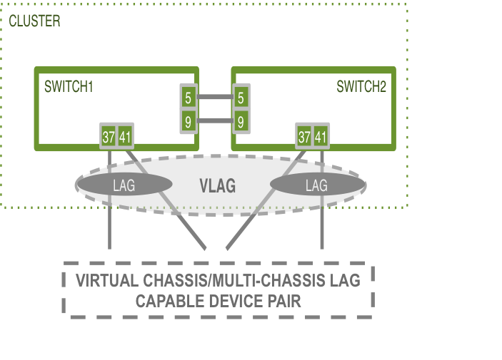
Figure 7-5 - Four-way vLAG between a Pluribus Cluster Pair and Another Multi-chassis LAG
Figure 7-6 below shows the common use case of interconnection of leaf and spline Pluribus clusters to provide high availability using the virtual chassis/four way vLAG technique.
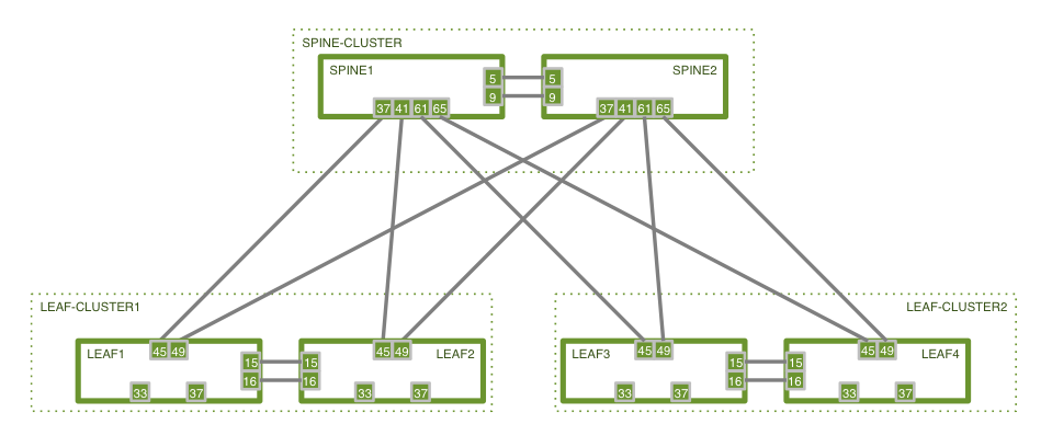
Figure 7-6 - Pluribus High Availability Cluster-based Spine/Leaf Design
In these network designs using active-active vLAGs (and cluster links), to prevent potential Layer 2 forwarding loops Netvisor ONE automatically installs special internal forwarding rules that drop any packets that would egress a vLAG port if the ingress port is found to be the cluster link.
On top of all of the above, clusters and vLAGs can also be used in conjunction with the standard VRRP technology to provide redundant active-active first-hop Layer 3 gateways to multi-homed end-points.
This capability is particularly important in the context of DCI designs, when used in conjunction with another standard technology, VXLAN, as we will see in a subsequent chapter.