
About Pluribus’ VXLAN Implementation and Benefits
If a network designer were tasked with selecting the best and most desirable technology among a number of implementation options, he or she would be hard pressed not to go with an open and standard approach. That is simply because a standard technology can maximize interoperability and hence offer network designers a wealth of software and hardware choices.
In contrast to other closed proprietary approaches, which require significant investments in complex and rigid hardware, Pluribus Networks has chosen the user-friendly path of a software-defined networking technology based on the VXLAN industry standard, where the fabric and its features seamlessly integrate with the advanced capabilities enabled by the VXLAN transport. (For more details on Pluribus’ fabric configuration, refer to the Setting up and Administering the Pluribus Fabric chapter.)
In particular, Pluribus has integrated the VXLAN implementation with the fabric’s capability of distributed MAC learning and VLAN transport, its redundant path support through vLAGs, virtual addresses and vRouters, as well as with the fabric VRFs’ distributed forwarding capability for maximum redundancy and scalability.
The power of the Unified Cloud Fabric distributed control plane has been leveraged to greatly augment and simplify VXLAN’s basic capabilities without requiring complex proprietary (and potentially not inter-operable) enhancements. Fabric VRFs and distributed multicast forwarding (described later in this section) are two examples of the powerful synergies that have been achieved.
As part of the Unified Cloud Fabric, two inter-related logical layers have to be designed and configured: the underlay and the overlay network.
Let’s look at each one individually.
About the Underlay Network’s Architecture
For flexibility and openness reasons, Pluribus engineers have decided to support a spectrum of different options based on standard protocols for fabric underlay architectures: they can be built using Layer 2 only, or with a combination of Layer 2 and Layer 3, or only with Layer 3, as shown in Figure 8-2 below.
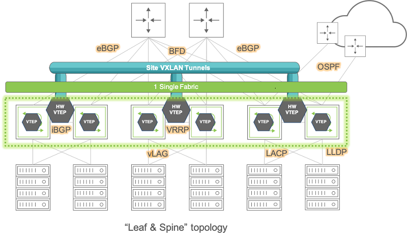
Figure 8-2: Pluribus Fabric Over Any Underlay Network
As depicted above, network underlays typically include both path and device redundancy.
As explained in the Configuring High Availability chapter, either with Layer 2 or with Layer 3 designs Pluribus supports switch clustering and vLAGs in order to minimize reliance on the Spanning Tree Protocol (in case of Layer 2 networks) as well as to optimize redundancy and failover speed.
For Layer 3 underlay networks Pluribus also supports standard routing protocols for device interconnection (such as OSPF and BGP) as well as the VRRP protocol when default gateway redundancy is required.
In particular, having the possibility of leveraging an IP-based routed transport for intra-DC and inter-DC interconnection makes the entire architecture more open and leaner, with the option to use any switch vendor in the core (since any vendor nowadays can provide a broad, inter-operable and robust support of Layer 3 technologies).
In summary, for the network underlay the designer will have to decide which topology and forwarding scheme to use, which devices to deploy in each network location, and, as explained earlier, will have to enable jumbo frames wherever the VXLAN transport is required (typically it is required end-to-end for pervasive deployment models).
Pluribus Networks’ open networking switches can be used as both leaf and spine switches, and can be connected to 3rd party switches, routers and appliances using just the aforementioned standard underlay technologies (whose configuration is described in detail in other chapters of this guide).
About the VXLAN Fabric Overlay and End Points
Regarding the VXLAN transport’s architecture and configuration, network designers have to decide where to place the VXLAN end points, i.e., the sources and the destinations of the VXLAN forwarding paths (referred to as tunnels in the RFC).
This decision depends on many different factors (such as level of software and hardware support, scalability, virtualization, traffic patterns, etc.) but the choice usually falls on the edge nodes of the fabric (whether hardware or software-based).
Redundancy can also be a key decision factor, as discussed in the next section.
A common scalable choice for end point (VTEP) placement is represented by the leaf switch(es), that is, the first-hop switches physically connected to the hosts (bare metal servers or VMs).
Furthermore, when configured in redundant pairs, leaf switches are the ideal locations for VTEP placement for improved service continuity, as shown in the figure below. (On the other hand, it is also possible that in certain other designs the VTEPs can be placed on spine switches, if so required by design prerequisites and/or network constraints.)
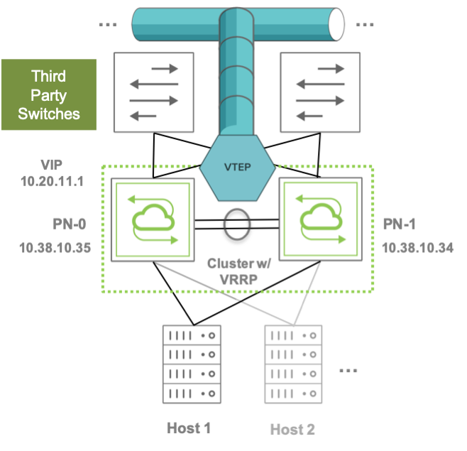
Figure 8-3: VTEP Placement on Leaf Switch Clusters
Pluribus switches support flexible VTEP placement. For example, VTEPs can be placed on pairs of Pluribus leaf switches that are connected to a third-party Layer 3 core network (as shown in the figure above), or they can be placed on pairs of Layer 3 Pluribus spine switches that interconnect two DC sites (or pods) over a generic IP-based network, or the design choice can even be a combination of the two above.
In any of these cases, the VXLAN traffic flows are terminated on the switches, which are responsible for encapsulating packets that arrive from servers or hosts on a Layer 2 network and transmitting them over to their destination. Similarly, the VXLAN packets arriving from the opposite direction are decapsulated and the inner packets are forwarded over to their destination end devices. The switches also collect traffic statistics, optimize ARP requests and MAC learning.
In addition to the above, Pluribus also supports scenarios in which VXLAN is not terminated on the switch itself, that is, in which the switch does not participate in the encapsulation and/or decapsulation of the VXLAN traffic.
In such case a host would typically implement a VTEP in software and therefore the switch would act mainly as an underlay node for the pass-through VXLAN traffic directed to that host.
On that VXLAN traffic, though, Netvisor ONE can still perform an important function:
Analytics collection: All TCP control packets as well as ARP packets traversing a tunnel are captured. By default, the ARP and TCP packets are captured only at the ingress and egress tunnel switches. With inflight analytics enabled, the analytics are captured on the traversing packets as well. These packets are used to build connection statistics and provide visibility as to which VXLAN nodes are on specific ports. With inflight analytics enabled, analytics packets are captured on the traversing packets.
About VTEP High Availability
A critical design requirement for various DC networks is to deploy the VXLAN transport in conjunction with a high availability (HA) configuration at the edge of the fabric. This guarantees path redundancy and service continuity in case of link or device failure at the edge.
In VXLAN parlance edge redundancy support is known as VXLAN Tunnel Endpoint High Availability (VTEP HA).
Pluribus switches support VTEP HA through the combination of multiple features: in particular, Pluribus implements a VTEP HA switch pair by harnessing the power of switch clustering in conjunction with the vLAG technology and with the standard VRRP protocol (these features are described in detail in the Configuring High Availability chapter).
This feature combination enables the configuration of redundant active-active Layer 3 switches that function as VRRP peers (with mutual liveliness checks) and that can provide a common virtual IP (VIP) address as active-active default gateway.
Thanks to the cluster synchronization function, a VTEP pair can act as a single logical VXLAN end point using a single shared VIP as source address. Similarly, a destination VXLAN end point can be reached by using its HA pair’s common VIP as destination address.
This interconnection of virtual IPs is exemplified in the figure below.
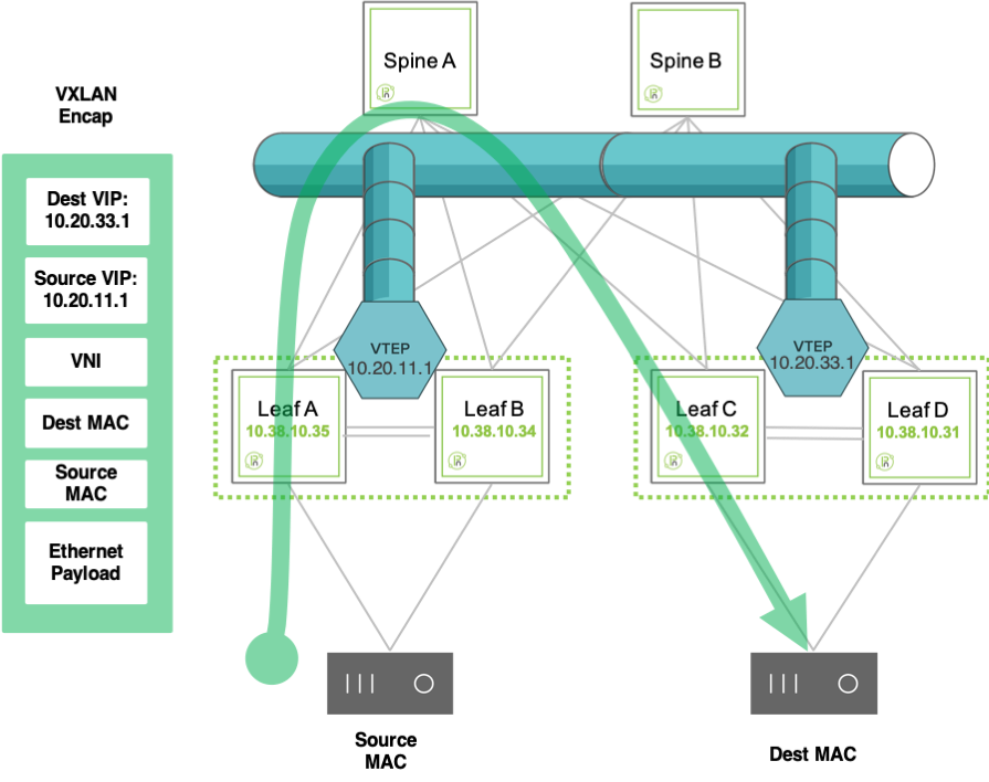
Figure 8-4: VIP Use for Inter-VTEP Communication
Setting up multiple of the above logical pairs enables the creation of an overlay network of interconnected VXLAN end points based on virtual (not physical) addresses which offers embedded physical as well as logical redundancy.
Configuration of these VXLAN pairs can be performed manually for each individual source and destination VTEP. However, Pluribus can further leverage the power of the Unified Cloud Fabric’s distributed control plane to automate this tedious and potentially error prone process (for more details refer to the VTEP configuration section below).
Similarly, configuration of VLAN extensions over a VXLAN fabric requires a standard VLAN ID to VXLAN Network ID (VNI) mapping scheme. This ID mapping process too can be repetitive and error-prone, but with Pluribus’ distributed control plane such global configuration can be propagated to all the nodes belonging to the same fabric instance, thus saving significant time and effort.
About the VXLAN Fabric Overlay and its Forwarding Optimizations
A fabric overlay comprises a number of VXLAN end point pairs, as mentioned above, whose interconnection is used to transport end stations’ traffic end-to-end based on their VLAN-to-VNI mappings.
A typical example of the logical overlay interconnect (of leaf switches in this instance) that VXLAN can be used to create over a physical underlay network is depicted in the figure below:
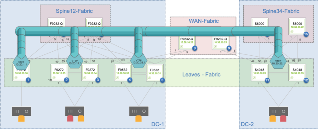
Figure 8-5: Overlay Network Interconnecting Single and Redundant VTEPs
Pluribus’ forwarding logic and distributed control plane employ the standard split horizon algorithm to create a loop-free logical forwarding topology in the fabric overlay network so as to steer any VXLAN traffic over it without creating potential switching loops.
Furthermore, the implementation of the forwarding logic does not require complex address tracking and propagation mechanisms (such as IETF’s MP-BGP-based EVPN solution). Pluribus instead uses its own native address registration and tracking technology, called vPort database, which is particularly useful to track host moves.
While a plain-vanilla hardware Layer 2 table is limited in its capacity by a switch’s dedicated ASIC memory size, the Netvisor ONE software runs in the control plane processor’s much larger DRAM memory space and hence is capable of tracking a large list of Layer 2 entries, much larger than what can fit into the limited space of a hardware table.
This logical software extension of the Layer 2 table is the vPort database, which can be considered as the authoritative distributed endpoint directory and switching activity history book of the entire Pluribus fabric.
In addition, as an optimization option (disabled by default), the fabric can use vPort information in conjunction with the ARP optimization technology to help manage the dynamic process of binding MAC/IP address pairs.
Pluribus’ ARP optimization technology harnesses the versatility of the vPort database to perform the dynamic endpoint discovery and ARP proxy functions that are required to support the mobility of end-points across the fabric, as described in the figure below.
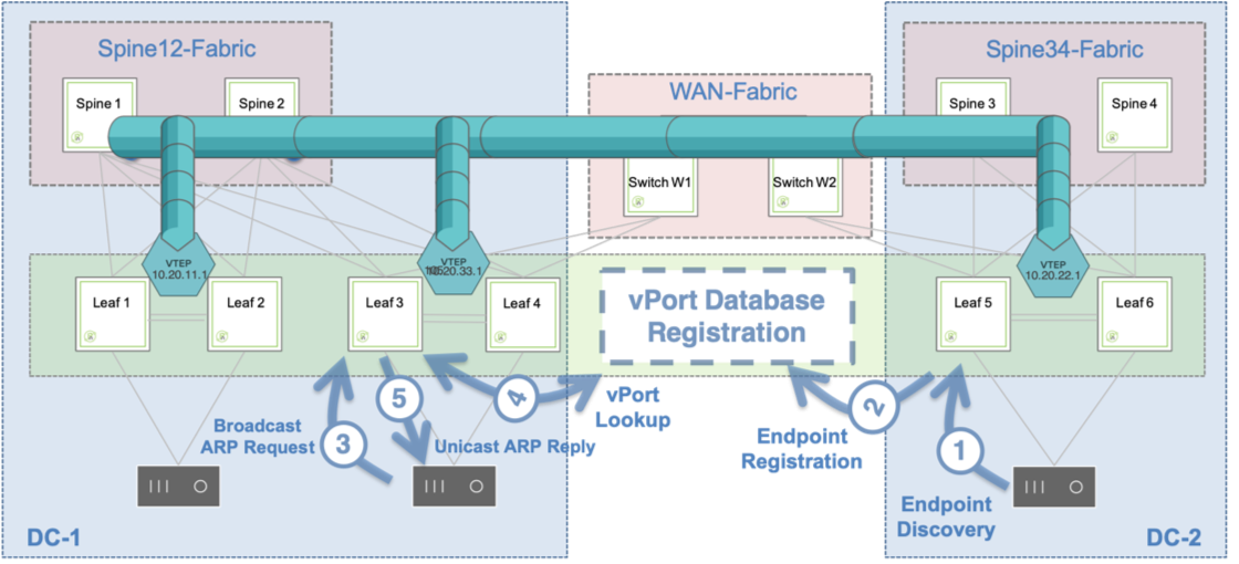
Figure 8-6: ARP Optimization Process
In the figure above, on the right-hand side a host is discovered through the traffic exchange with its neighboring switch. As a consequence, its information is recorded in the vPort database.
On a remote switch (on the left-hand side of the figure) whenever someone sends a broadcast ARP request to learn about the MAC address associated with the IP address of the newly discovered host, an ARP suppression function is executed.
In other words, the ARP response comes proxied from the fabric based on the contents of the distributed vPort database, which is available on all fabric nodes. Therefore, there is no need for any direct ARP communication between requester and registered host, nor for any flooding of broadcast ARP packets.
Note: The ARP optimization can be useful in various scenarios but may also impact the CPU utilization of the switches. Therefore, it is disabled by default and its use needs to be evaluated on a case-by-case basis.
Moreover, starting from release 2.6.0, Pluribus has added a further under-the-hood enhancement to the fabric’s control plane logic that significantly reduces the need for the less-than-optimal ‘flood and learn’ scheme for unknown destination traffic.
This enhancement, called vPort forwarding, implements a more optimized forwarding logic thanks to the versatility of the vPort database: this logic is analogous to ARP optimization’s use of the vPort database information to avoid unnecessary ARP flooding, but it’s applied to the general case when the destination Layer 2 address of a generic packet can be successfully looked up in the distributed vPort database so as to avoid having to flood the packet to all its possible destinations.
About ECMP Load Distribution for VXLAN Traffic
Equal-cost multi-path routing (ECMP) is a routing strategy where next-hop packet forwarding can occur over multiple paths on a per flow basis.
Hardware platforms usually perform a hash function on a number of packet fields to perform path selection and determine the load balancing traffic distribution.
In case of VXLAN-encapsulated traffic, for backward-compatibility purposes, the same legacy ECMP algorithm can be applied to VXLAN packets too without requiring deeper inspection.
This is because the VXLAN RFC recommends that the encapsulation function add some amount of entropy to a VXLAN packet by generating a variable source UDP port:
Source Port: It is recommended that the UDP source port number be calculated using a hash of fields from the inner packet -- one example being a hash of the inner Ethernet frame's headers. This is to enable a level of entropy for the ECMP/load-balancing of the VM-to-VM traffic across the VXLAN overlay.
In other words, that recommendation makes sure that some amount of variability is present when creating VXLAN connections so that they can be easily load-balanced using most ECMP functions implemented by networking platforms.
In particular, any ECMP algorithm that takes into account (also) the Layer 4 source port for path determination will be able to take advantage of the level of entropy added to the VXLAN packets as per the RFC.
In case of Netvisor ONE this is achieved by default by implementing a granular 7-tuple hashing scheme that uses the following fields: source IP address, destination IP address, VLAN number, destination Layer 4 port, source Layer 4 port, IP protocol number, source physical port.
Other networking devices may use a simpler ECMP configuration referred to as 5-tuple hashing, which includes just the source and destination IP addresses, the protocol type, and the source and destination Layer 4 ports for UDP or TCP flows.
Adding VXLAN traffic entropy and applying ECMP hashing are basic hardware functions supported by default on Pluribus switches. These functions are supported by most 3rd party switches and routers as well.
See also the Displaying ECMP Load Balancing Info for VXLAN section.
About VXLAN Routing
In most designs the VXLAN overlay network requires that overlay traffic be routed as well as bridged.
This is typically required for the host traffic to be routed across VNI-mapped VLANs and/or to reach the data center gateways, firewalls (or other L3/L4 appliances), so as to be forwarded to the Internet. The reverse path from the Internet also requires that the traffic be routed as well to reach the hosts.
Note: Pluribus also refers to VXLAN routing with the acronym RIOT, which stands for Routing In and Out of Tunnels.
For hosts on different VLANs to communicate with each other and with the Internet, a cluster of border leaf switches is deployed for redundancy and load splitting purposes to become the overlay network’s default gateway. VLAN interfaces are configured as required by the network administrator on the cluster’s vRouters (up to 32 vRouters are supported).
This model is sometimes referred to as centralized routing for the VXLAN fabric (as opposed to the distributed routing model implemented with VRFs, as explained in a subsequent section).
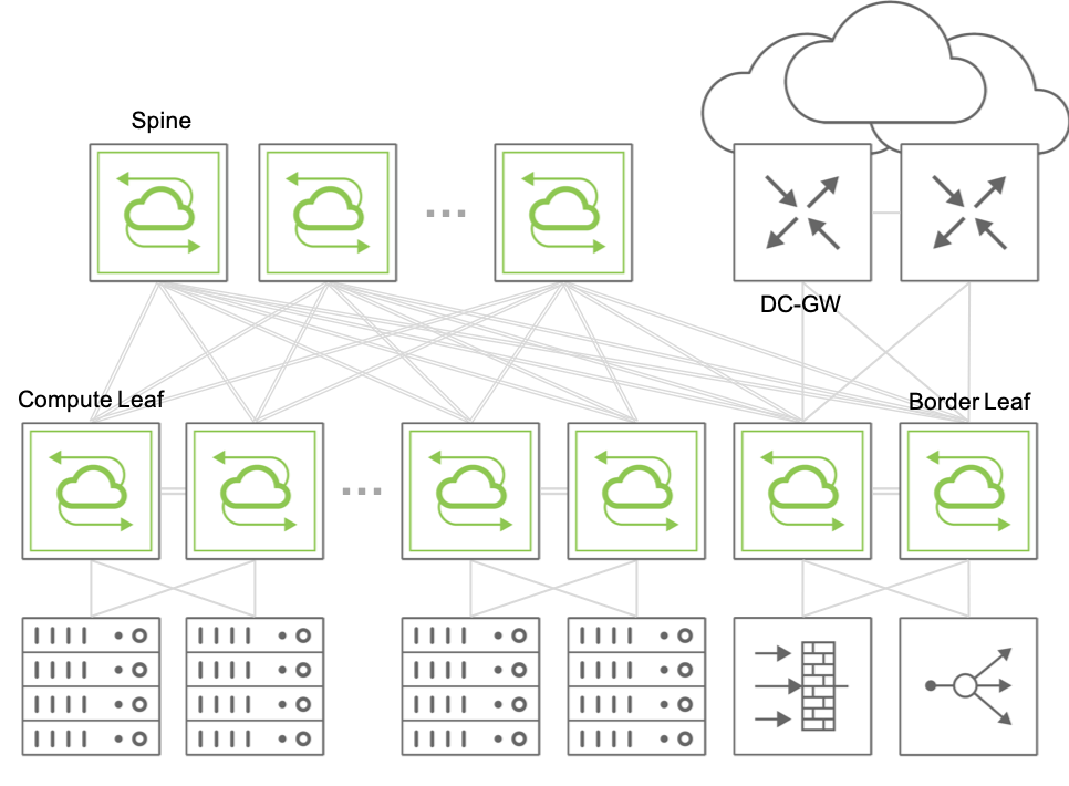
Figure 8-7: Example of Fabric Design Using Centralized Routing
In the centralized routing model, any fabric packets that need to be routed between two hosts in different VNI-mapped VLANs are sent to a centralized overlay vRouter and then VXLAN-encapsulated or -decapsulated depending on source and/or destination’s host location.
When multiple sequential hardware operations are required, such as in the forwarding –> decapsulation –> routing sequence, or in the reverse routing –> encapsulation –> forwarding sequence (or also when any packet replication is needed), Pluribus leverages the hardware’s capabilities to implement multiple packet lookup and rewrite passes using a technology called recirculation (or hardware loopback).
This technique is used whenever a certain switch model is incapable of applying all the necessary operations to certain traffic in a single instance (that is, in a single pass). Hence, such traffic will have to be recirculated at least once through the hardware forwarding engine.
Pluribus supports the recirculation technique with the dedicated vxlan-loopback-trunk configuration.
About the VXLAN Loopback Trunk
Netvisor ONE uses the vxlan-loopback-trunk configuration command to set aside a number of (internal or front-panel) ports that are configured as a logical group (i.e., a dedicated port channel) for recirculation.
This special trunk link is auto-created and is reserved to be used to carve out the necessary amount of bandwidth required for the recirculation of packets.
Typically, the network administrator allocates a number of ports (e.g., 2 or more for redundancy purposes) to a VXLAN loopback trunk that is sufficient to provide an amount of aggregate bandwidth in excess of what is required for routing and/or replication of all Broadcast/Unknown Unicast/Multicast (BUM) VXLAN traffic.
From an operational standpoint, if a packet needs to be recirculated after decapsulation as part of the routing operation, Layer 2 entries for the vRouter MAC address or the VRRP MAC address on VNI-mapped VLANs are programmed to point to the vxlan-loopback-trunk link in hardware.
Therefore, to verify that the traffic can be recirculated, the network administrator can simply look at output of the l2-table-show command, which should display a special vxlan-loopback flag to indicate the recirculation-related hardware state (see also the Checking VXLAN Recirculation L2 and L3 Entries section below).
In summary, it is important to size the VXLAN loopback trunk appropriately and, in certain cases, it may be helpful to verify the operational state of the Layer 2 entries associated to it in the hardware tables.
When monitoring the fabric, it is also useful to periodically check the hardware recirculation counters (as discussed in the Showing VXLAN Trunk Replication Counters below) so that the network admin can stay abreast on the peak recirculation bandwidth needs of the various fabric switches.
For sizing purposes, note that the VXLAN loopback infrastructure is used for routing traffic before VXLAN encapsulation and/or after VXLAN decapsulation. It is also used for bridging broadcast , unknown unicast or multicast (BUM, in short) traffic in the overlay network.
On the other hand, non-routed known unicast traffic is forwarded and encapsulated, or decapsulated and forwarded, in one single pass without requiring the VXLAN loopback trunk.
Starting from Netvisor ONE releases 6.0.0 and 6.0.1 new single-pass configurations are supported on certain switch models using newer hardware forwarding engines. In particular, it is possible to enable single-pass unicast VXLAN routing, single-pass broadcast/unknown unicast and multicast flooding, as well as single-pass distributed multicast bridging. Therefore, by leveraging these hardware capabilities when supported, it is possible to eliminate the need for loopback trunks in certain configurations. For more details, refer to the Configuring the VXLAN Loopback Trunk section.
About the VXLAN Configuration Models
Netvisor ONE offers three powerful VXLAN configuration models.
The first model is aimed at full configuration automation and therefore is likely to be used more often. It leverages a special configuration abstraction called a VTEP object. When VTEP objects are created on the nodes, they trigger the automatic creation of VXLAN tunnels from such nodes, thus creating a full mesh of bidirectional connections between the nodes. In addition, starting from Netvisor ONE release 6.0.0 it is possible to automatically add a certain VLAN/VNI pair to all the VXLAN connections with the auto-vxlan keyword (note that, if the VNI value is not specified by the user, it is picked automatically by the system provided that the configuration scope is fabric.)
This any-to-any model is the most convenient one to quickly set up a full VXLAN fabric between multiple leaf nodes and associate to it all of the configured VLAN/VNI mappings. For more details, refer to the Configuring VTEP Objects with Automatic Fabric Connections section.
Figure 8-8 shows an example of mesh with three leaf nodes configured with three VTEP objects.
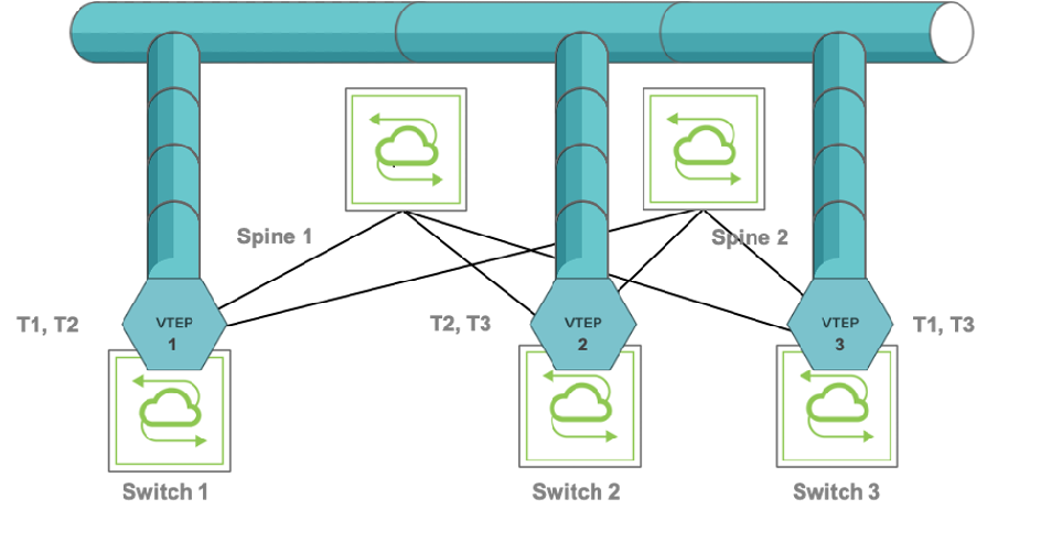
Figure 8-8: Example of VTEP Object Configuration
Bidirectional connections T1 through T3 are called auto-tunnels because they are automatically configured by the system when the VTEP objects are created with the vtep-create command. See the Configuring VTEP Objects with Automatic Fabric Connections section below for the naming of the tunnels automatically generated for the topology in Figure 8-8.
The second model is more granular because it requires more explicit configuration, as it doesn’t use the auto-vxlan feature (which also means it does not require release 6.0.0 or later).
In this scenario, the user may not want to extend all the VNIs to all the VTEPs and their mesh of VXLAN connections. The user may instead want to extend a VNI, say, to VTEP1 and VTEP2 only (in the figure above) by using the vtep-vxlan-add command selectively. In such case, only two tunnels are automatically created between VTEP1 and VTEP2 for the chosen VNI (the two auto-tunnels are represented by the bidirectional T2 connection in the figure above), whereas T1 and T3 would not be created for the specific VNI per explicit user choice.
In this model, semi-manual establishment of VXLAN connections is required since the user is responsible to explicitly select which VNIs should be added to each VTEP.
Starting from Netvisor ONE release 6.0.1 a third model has been introduced: it’s the hub-and-spoke configuration model. When used in conjunction with bridge domains, it mimics the behavior of the Metro Ethernet Forum (MEF) E-Tree service.
This model leverages a new keyword, isolated, and is not compatible with the auto-vxlan assignment. The VTEP on the hub node is configured normally, just as in case 2 above, whereas the VTEPs on the spokes are configured with the isolated keyword because they are not supposed to communicate with each other.
Figure 8-9 below shows an example of hub-and-spoke VXLAN topology where the hub node has bidirectional connections to the spokes but the spokes don’t have connections between each other.
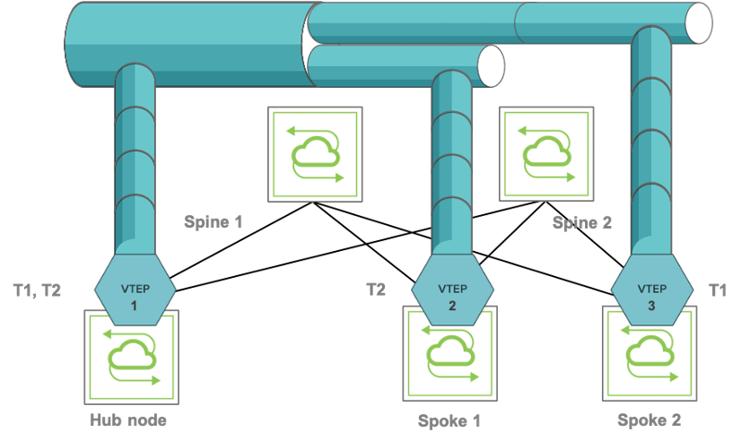
Figure 8-9: Example of Hub-and-spoke VXLAN Configuration
Note: The above two figures actually show a virtual connection view on a per-VNI basis: that means that tunnels are automatically created but then it’s the per-VNI connectivity policy that determines whether nodes associated with each VNI are actually connected in a virtual mesh or in a virtual hub-and-spoke configuration.
For configuration details and examples, refer to the Configuring VTEP Objects with Automatic Fabric Connections section below.