
Configuring Active-Active vLAGs: a Step-by-Step Example
Note: As displayed in Figure 7-9, there must be a physical connection between PN-0 and PN-1 before you can configure a vLAG.
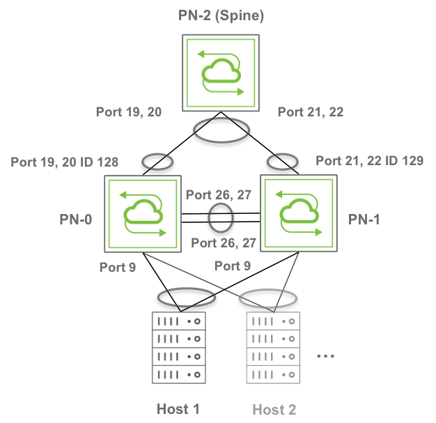
Figure 7-9 - Active-Active vLAGs Toward a Dual-Homed Host and a Spine Switch
The sample topology in Figure: Active-Active vLAGs Toward a Dual-Homed Host and a Spine Switch above comprises three Pluribus switches that are part of the same fabric instance, fab-vLAG. The spine switch is set as RSTP root.
It’s important to note that ports 19-20 on PN-0 and ports 21-22 on PN-1 are connected to PN-2 (Spine). Ports 26, 27 interconnect PN-0 and PN-1 for the cluster link configuration required to set up a vLAG.
You can use the following steps to configure the above-pictured configuration with active-active vLAGs.
1) On the spine switch PN-2 use the following command:
CLI (network-admin@switch) > stp-modify bridge-priority 4096
2) Create the fabric and add the switches to it. On PN-2 use the fabric-create command:
CLI (network-admin@switch) > fabric-create name fab-VLAG
On PN-0 and PN-1 join the fabric:
CLI (network-admin@switch) > fabric-join name fab-VLAG
CLI (network-admin@switch) > fabric-join name fab-VLAG
3) Create VLAN connectivity from the spine switch all the way to the host. On PN-2 create for example VLAN 25 with scope fabric:
CLI (network-admin@switch) > vlan-create id 25 scope fabric
On PN-0 and PN-1 add VLAN 25 and untag the port connected to the host:
CLI (network-admin@switch) > vlan-port-add vlan-id 25 untagged ports 9
CLI (network-admin@switch) > vlan-port-add vlan-id 25 untagged ports 9
On PN-0 and PN-1 make the port connected to the host be an edge port:
CLI (network-admin@switch) > stp-port-modify port 9 edge
CLI (network-admin@switch) > stp-port-modify port 9 edge
4) Create a cluster configuration between PN-1 and PN-0. This creates the cluster link between ports 26, 27. On PN-0 enter the cluster-create command:
CLI (network-admin@switch) > cluster-create name VLAG cluster-node-1 PN-0 cluster-node-2 PN-1
5) In this example, for simplicity’s sake we will use static trunks toward the spine switch to create a vLAG. (LACP’s active mode can be used too, instead of off mode.) In this case you would first disable ports between PN-2 and PN-0 and then create a static trunk between them. Therefore, on PN-0 modify the ports facing PN-2 like so:
CLI (network-admin@switch) > port-config-modify port 19,20 disable
6) Create a two-port trunk between PN-0 and PN-2 with those ports:
CLI (network-admin@switch) > trunk-create name pn0-to-pn2 ports 19,20 lacp-mode off
CLI (network-admin@switch) > trunk-show format all layout vertical
switch: PN-0
trunk-id: 128
name: pn0-to-pn2
ports: none
speed: disable
egress-rate-limit: unlimited
autoneg: off
jumbo: on
enable: off
lacp-mode: off
lacp-priority: 0
lacp-timeout: slow
lacp-fallback: bundle
lacp-fallback-timeout: 50
lacp-individual: none
stp-port-cost: 2000
stp-port-priority: 128
reflect: off
edge-switch: no
pause: no
description:
loopback: off
receive-only: on
unknown-ucast-level: %
unknown-mcast-level: %
broadcast-level: %
lport: 0
rem-rswitch-port-mac: 00:00:00:00:00:00
rswitch-default-vlan: 0
status:
config:
trunk-hw-id: 0
send-port: 4294967295
routing: yes
host-enable: no
From the above output, you can verify the name and ID of the trunk configuration pn0-to-pn2. You need this information to create the vLAG.
7) On PN-1 repeat the same commands to create a static two-port trunk (LACP mode off) between PN-1 and PN-2. You would, therefore, disable ports between PN-2 and PN-1 and then create a static trunk between them. On PN-1 modify the ports facing PN-2 like so:
CLI (network-admin@switch) > port-config-modify port 21,22 disable
CLI (network-admin@switch) > trunk-create name pn1-to-pn2 ports 21,22 lacp-mode off
CLI (network-admin@switch) > trunk-show format all layout vertical
switch: PN-1
intf: 129
name: pn1-to-pn2
port: 21-22
speed: 10g
autoneg: off
jumbo: off
enable: off
lacp-mode: off
lacp-priority: 32768
lacp-timeout: slow
reflect: off
edge-switch: no
pause: no
description:
loopback: off
mirror-only: off
lport: 0
rswitch-default-vlan: 0
port-mac-address: 06:60:00:02:10:80
status:
config:
send-port: 0
8) Create the vLAG from the bottom switches going upstream. Keep one side of the vLAG disabled while you configure this step. On PN-0 use the vlag-create command:
CLI (network-admin@switch) > vlag-create name to-spine port 128 peer-port 129 peer-switch PN-1 lacp-mode off mode active-active
On PN-2 create a normal 4-way trunk with the name trunk-pn:
CLI (network-admin@switch) > trunk-create name trunk-pn ports 19,20,21,22 lacp-mode off
9) Enable ports on all switches. On PN-2, PN-0 and PN-1 enter the port-config-modify command:
CLI (network-admin@switch) > port-config-modify port 19,20,21,22 enable
CLI (network-admin@switch) > port-config-modify port 19,20 enable
CLI (network-admin@switch) > port-config-modify port 21,22 enable
10) As a final step, create the server-facing active-active vLAG. In this case we will make it dynamic (LACP mode active). On PN-0 enter the vlag-create command:
CLI (network-admin@switch) > vlag-create name to-host port 9 peer-port 9 peer-switch PN-1 lacp-mode active mode active-active
Display and verify the vLAG configuration information:
CLI (network-admin@switch) > vlag-show format all layout vertical
id: a000024:0
name: to-host
cluster: VLAG
mode: active-active
switch: PN-0
port: 9
peer-switch: PN-1
peer-port: 9
failover-move-L2: no
status: normal
local-state: enabled, up
lacp-mode: active
lacp-timeout: slow
lacp-key: 26460
lacp-system-id: 110013777969246