
Configuring OVSDB High Availability
Netvisor ONE supports the OVSDB high availability feature where OVSDB instances are configured on both the switches in a cluster to ensure redundancy. The ODL controller pushes vNET-specific configuration to the OVSDB schema in both the cluster nodes while the VTEP agent in the master node provisions the overlay as stipulated by the tables in the schema. The VTEP agent in the slave node does not act upon the configuration updates from the SDN controller since the VTEP agent in the slave node is passive. In the occasion of a failover, the slave node becomes the master node and the VTEP agent in the master node provisions the network.
Note: When the cluster goes offline, both the nodes operate in standalone mode which may result in divergent configurations.
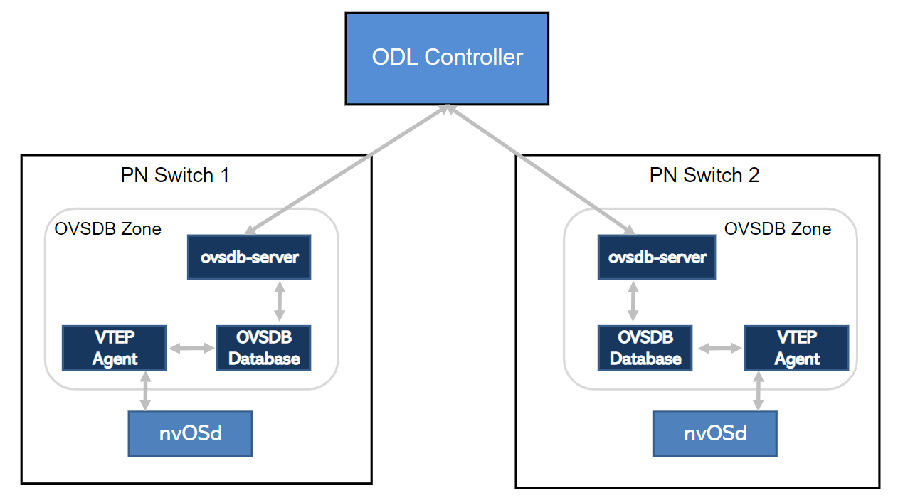
Figure 20-2 - OVSDB High availability
To configure High availability for OVSDB, follow the steps below:
- Configure the vNET for the cluster with private VLANs, VXLANs, and managed ports:
CLI (network-admin@switch1) > vnet-create name vpod1 scope fabric vlan-type private num-private-vlans 100 managed-ports 12 vxlans 10000-10099
- Create a VLAN with cluster scope for OVSDB HA configuration:
CLI (network-admin@switch1) > vlan-create id 60 scope cluster description ovsdb-ha ports 272
- Configure vRouter underlay on switch1 and create VRRP interfaces:
CLI (network-admin@switch1) > vrouter-create name vpod1-vr1 vnet vpod1 router-type hardware hw-vrrp-id 10
CLI (network-admin@switch1) > vrouter-interface-add vrouter-name vpod1-vr1 ip 10.10.10.1/29 vlan 60 vlan-type public
CLI (network-admin@switch1) > vrouter-interface-add vrouter-name vpod1-vr1 ip 10.10.10.3/29 vlan 60 vlan-type public vrrp-id 10 vrrp-primary eth1.60 vrrp-priority 250
- Configure vRouter underlay on switch2 and create VRRP interfaces:
CLI (network-admin@switch2) > vrouter-create name vpod1-vr2 vnet vpod1 router-type hardware hw-vrrp-id 10
CLI (network-admin@switch2) > vrouter-interface-add vrouter-name vpod1-vr2 ip 10.10.10.2/29 vlan 60 vlan-type public
CLI (network-admin@switch2) > vrouter-interface-add vrouter-name vpod1-vr2 ip 10.10.10.3/29 vlan 60 vlan-type public vrrp-id 10 vrrp-primary eth3.60 vrrp-priority 200
Note: The VRRP interfaces on switch1 and switch2 share the same virtual IP address.
- Configure and deploy TLS certificates for both the cluster nodes if you want to establish an SSL connection between OVSDB instances and the ODL controller. For configuration steps, see Using OpenSSL TLS certificates for OVSDB and other Services.
- Configure Open vSwitch on switch1 and create OVSDB interface:
CLI (network-admin@switch1) > openvswitch-create name ovs-ha-1 vnet vpod1 tunnel-ip 192.168.0.1 gateway 10.10.10.3 cert-name cert1 ca-cert-name ca-cert1
CLI (network-admin@switch1) > openvswitch-interface-add ovs-name ovs-ha-1 ip 10.10.10.100 netmask 24 vlan 3001 vlan-type public
- Configure Open vSwitch on switch2 and create OVSDB interface:
CLI (network-admin@switch2) > openvswitch-create name ovs-ha-2 vnet vpod1 tunnel-ip 192.168.0.2 gateway 10.10.10.3 cert-name cert1 ca-cert-name ca-cert1
CLI (network-admin@switch2) > openvswitch-interface-add ovs-name ovs-ha-2 ip 10.10.10.103 netmask 24 vlan 60 vlan-type public
- Configure the connection to the ODL controller on switch1:
CLI (network-admin@switch1) > opensvswitch-hwvtep-manager-add name ovs-ha-1 manager-type odl connection-method ssl ip 20.20.20.1
- Configure the connection to the ODL controller on switch2:
CLI (network-admin@switch2) > opensvswitch-hwvtep-manager-add name ovs-ha-2 manager-type odl connection-method ssl ip 20.20.20.1