
Understanding Pluribus VXLAN EVPN Technology
Pluribus Networks’ Unified Cloud Fabric offers a highly flexible approach to software-defined networking (SDN) with native support for the VXLAN transport with an optimized control plane.
As described in the Configuring VXLAN chapter earlier, the Pluribus fabric uses the VXLAN overlay technology for intra-fabric connectivity. It supports the creation of static VXLAN-based tunnels using the tunnel-create command. It also supports automatic tunnel creation through the VTEP object construct and its associated commands.
VTEP objects are fabric-scoped, making all the nodes aware of each other’s VTEPs and their VNIs. Furthermore, fabric-wide Layer 2 and Layer 3 reachability information is propagated to each node inside a fabric through vPort data synchronization. Remote reachability data is leveraged to avoid the need to flood and learn packets. Hence, traffic forwarding is optimized.
Multi-tenancy is supported too by using highly scalable hardware-based VRF segmentation.
In this context, the EVPN technology’s BGP-based control plane offers a unique opportunity to further augment the fabric’s flexibility and provisioning simplicity in complex multi-pod data center network designs.
As we will describe in the following, the Pluribus Unified Cloud Fabric has been extended to integrate the EVPN standard as a means to improve the fabric’s scalability and interconnection options between data center pods, as well as to support multi-vendor interoperability.
Starting from Netvisor ONE release 6.1.0, Pluribus Networks implemented the EVPN technology to interconnect multiple fabric pods and to extend the VXLAN overlay across them, supporting both IPv4 and IPv6. EVPN’s powerful control plane enables network architects to build larger scale multi-pod designs, where each pod can comprise up to 32 leaf nodes. It also allows a Pluribus pod to interoperate with pods using third party vendors’ nodes.
In this implementation, VTEP objects, subnets, VRFs are naturally extended to communicate across pods. To do that, Netvisor ONE leverages EVPN in a pragmatic, integrated and standards-compatible way to implement a BGP-based control plane that enables multi-hop VXLAN-based forwarding across pods using a number of key fabric enhancements, described in the following.
About EVPN Border Gateways
In Pluribus’ fully interoperable implementation, EVPN’s message exchange is supported only on specially designated border nodes, deployed individually or in redundant pairs (i.e., in clusters running VRRP).
Such border nodes are commonly called Border Gateways (BGW), as they implement the EVPN Border Gateway functions (which we will describe in detail in the following sections). In essence, they are in charge of exchanging messages with external EVPN-capable nodes (Pluribus or other vendors’ devices) and of propagating and translating external EVPN routes, where needed, within each pod, as depicted in the figure below.
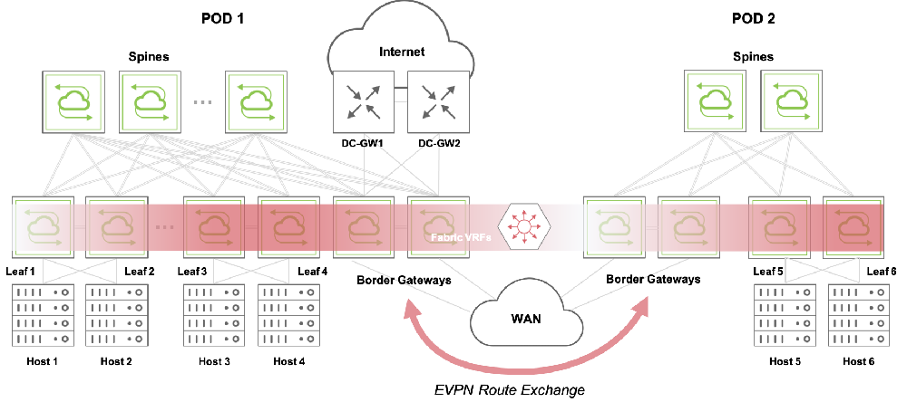
Figure 10-1: Border Gateways and EVPN Route Exchange
Border gateway nodes are identified by a special vRouter configuration that includes two steps: the vRouter must be configured with the evpn-border parameter and must have at least one BGP neighbor set to l2vpn-evpn, as described in more detail in the configuration section below.
Note: The VXLAN EVPN border gateway functions are supported only on the Dell S5200 Series.
Note: As of Netvisor ONE release 6.1.0, only leaf nodes can be designated as border gateways.
About Border Gateway Functions
EVPN border gateways implement a number of key control plane and data plane functions that guarantee multi-fabric interconnection and interoperability.
By leveraging them, Netvisor ONE can seamlessly extend VTEP objects, VNIs, subnets and VRFs across fabrics by simply leveraging the EVPN control-plane capabilities. Such capabilities are based on special route types specified by the standards.
Netvisor ONE supports the following EVPN route types:
- Type 2 routes, i.e., MAC/IP advertisement routes, as defined in RFC 7432. They are required to propagate MAC learning information (and optionally associated IP addresses) for device reachability purposes over a so-called Layer 2 VNI (L2VNI). Additionally, MAC/IP advertisements are used to propagate host route information.
- Type 3 routes, i.e., Inclusive Multicast Ethernet Tag routes, as defined in RFC7432. They are required for Broadcast, Unknown Unicast and Multicast (BUM) traffic delivery across EVPN networks. They are used to propagate VTEP and VNI information.
- Type 5 routes, i.e., IP Prefix routes, as defined in the EVPN Prefix Advertisement Internet Draft. This new type was added to advertise IP prefixes independently from MAC addresses (i.e., without relying on type 2 routes). They are used to advertise subnets and VRF information (the so-called Layer 3 VNIs).
The above standard route types are used to implement various networking functions:
Type 2 Route Translation Function
For inter-fabric broadcast domain and Layer 2 learning extension, border gateways translate Type 2 routes received from their peers to Netvisor ONE’s vPort synchronization messages within the local fabric. Vice versa, they also translate local vPort synchronization messages to Type 2 routes and then send them over to their peers.
In other words, they act as ‘language translators’ because they import and export Layer 2 information to and from external EVPN nodes to keep both local and remote fabric nodes in sync.
Type 3 Route Distribution Function
To implement VXLAN-based connectivity, Netvisor ONE supports special configuration constructs called VTEP objects, which automatically create a mesh of tunnels between each other to establish a fabric overlay network.
VTEPs can be configured within a fabric pod or can be external to a pod (in which case their location is called host-external). See the Configuring VTEP Objects with Automatic Fabric Connections section for more details.
Border gateways act as proxies for the communication of the local fabric with remote VTEP objects, for the inter-pod automatic tunnel creation and the VNI configuration.
They leverage EVPN Type 3 routes to propagate VTEP and VNI information within BGP messages.
Such information is used with a local scope by border gateways to automatically create host-external VTEPs to locally represent the remote border gateways’ VTEP objects. In other words, these special VTEPs are proxy representations of the neighbor VTEPs in the local border gateways (for an example, refer to the configuration section below).
The name of the Type 3 route-derived external VTEPs contains the __evpn__ prefix string to make them easily identifiable (and also to distinguish them from manually created host-external VTEPs). The name also contains the (virtual) IP address of the corresponding remote VTEP object.
The VNI information exchanged in Type 3 routes is used to compare the VNIs configured on the local VTEPs with those configured on the remote ones. If there is at least one local VNI matching an external one, VXLAN tunnels are automatically established with the neighbor EVPN VTEPs from the local ones (see Figure 10-2 below for a visual representation). The automatic tunnel naming scheme prefixes the auto-tunnel- string to the source and destination VTEP IPs. (For more details and examples, see the configuration section below.) VNIs are added and removed dynamically based on receipt of Type 3 routes.
In summary, once VTEP objects are configured by the user in the different pods, border gateways act as inter-fabric translators of Type 3 routes to and from Netvisor ONE synchronization messages. This guarantees the full automation of the overlay creation process, not just within a single local pod but also across pods.
In addition, border gateways act as (individual or redundant) traffic forwarders for bridged traffic within the same broadcast domains.
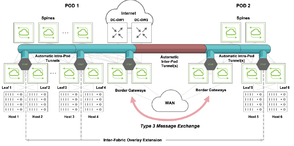
Figure 10-2: Inter-pod VXLAN Connections
Border gateways can also act as traffic forwarders for routed traffic, but that requires an additional key function as described next.
Type 5 Route Distribution Function
Netvisor ONE supports the configuration of subnet objects and VRF instances as a way to perform distributed VXLAN routing in hardware with multitenancy, as described in the Configuring Unicast Fabric VRFs with Anycast Gateway section.
EVPN border gateways can be used to extend subnets and associated VRFs across fabrics. For that purpose, they employ type 2 and type 5 routes which they send to their remote gateway peers to notify them of remote subnets and hosts. As a consequence, the remote border gateways can install into their routing tables prefix routes and host routes corresponding to any active remote subnets and known hosts.
In addition, subnets are associated to VRFs for route table entry segregation purposes. With EVPN, these VRFs have to be uniquely identified as part of the inter-fabric synchronization process: this task is achieved by introducing a new type of VNI, called Layer 3 VNI, which is uniquely associated to each VRF and is exchanged through EVPN messages between border gateways.
About Inter-Pod VXLAN Routing with Subnet Objects
When deploying subnets in a multi-pod topology running EVPN, in Pluribus parlance subnets can be of three types:
- local (when present only in the local pod relative to a border gateway)
- remote (when located on a pod different from the local one)
- stretched (when present in two or more pods).
Note: Having a stretched subnet does not necessarily mean that there are hosts in that subnet connected to all nodes. Hosts can be connected only to a subset of the nodes.
VXLAN routing between them is possible provided certain basic configuration rules are observed:
- A local subnet must be present on all leaf nodes: for ease of configuration, that can be achieved by using fabric scope in the subnet creation command.
- Subnets’ L2 VNIs and prefix lengths must be configured consistently across all pods.
- VRFs’ L3 VNIs must be configured consistently across all pods.
- As shown in Figure 10-3 below, if needed, data center gateways should be connected to the border gateways for routing of North-South traffic.
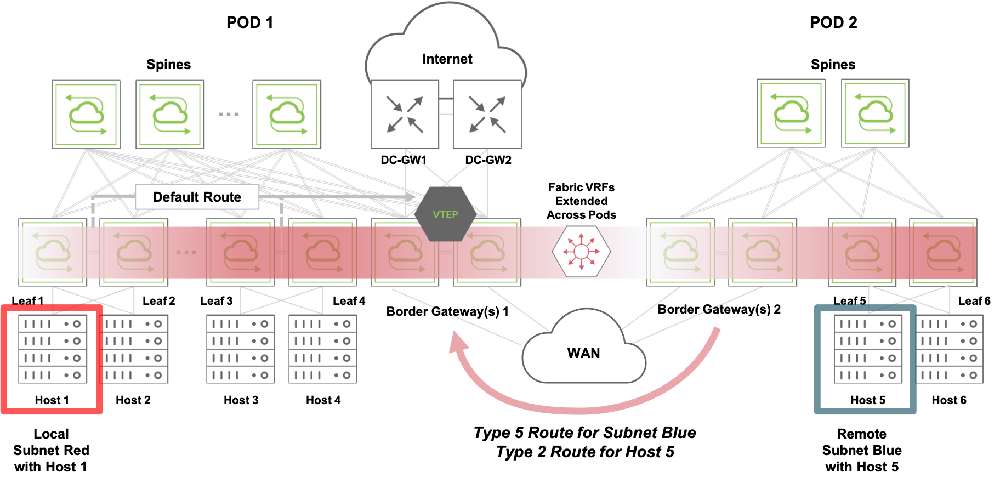
Figure 10-3: Control Plane for Inter-Pod VXLAN Routing (from Host 1 to Host 5)
In addition to the above configuration guidelines, some key automation is performed by the fabric when subnets are created: as depicted in Figure 10-3, border gateways propagate local subnet information with Type 2 and Type 5 messages to their EVPN peers. Such peers then send special messages to their local fabric nodes (that are not border gateways) to automatically install a default route pointing to their border gateways’ VTEP IP address. VXLAN traffic can then be routed to any remote pod (for example from Host 1 to Host 5, as depicted the figure above) using the two hop model described in the following section.
About Packet Flows for Inter-Fabric Forwarding
Let’s analyze how forwarding is performed from a local subnet to a remote one, and then from a local subnet to a stretched one.
Local to Remote Subnet Forwarding
In this forwarding example, Host 1 in the local subnet (Red) needs to send a packet to Host 5 in a remote subnet (Blue), as already shown in Figure 10-3.
In this scenario, as explained earlier, Border Gateways 2 (configured as a redundant pair) send Type 2 and Type 5 information to Border Gateways 1 regarding Host 5 and subnet Blue.
The fabric automation also makes sure that a default route points to Border Gateways 1’s VTEP virtual address on leaf nodes 1, 2, 3 and 4. So when a packet needs to be sent from Host 1 to Host 5, a two hop forwarding process is performed as described in the next figure:
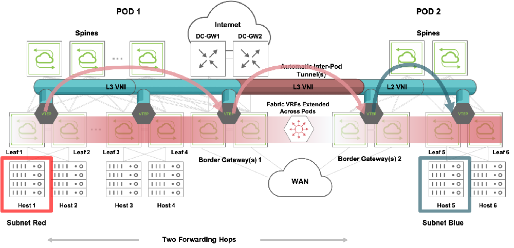
Figure 10-4: Two Hop VXLAN Routing
The packet from Host 1 is first routed to redundant Border Gateways 1 (per default route) over a VXLAN tunnel based on the VRF’s L3 VNI.
Then, using the same L3 VNI, the packet is routed over a different tunnel to redundant Border Gateways 2 as the next hop. This intermediate tunnel is automatically created between the peer VTEPs of Border Gateways 1 and 2.
Lastly, when the packet reaches Border Gateways 2, the final routing from L3 VNI to subnet Blue is performed over a tunnel using subnet Blue’s L2 VNI. In case the adjacency for Host 5 is not yet resolved, an ARP request is broadcast by the border gateway to all the devices in the subnet to learn about the destination address.
This multi-hop routing lookup model is also known as symmetric routing. The split horizon rule must be followed when forwarding VXLAN traffic in and out of tunnels to avoid traffic looping.
Local to Stretched Subnet Forwarding
When a subnet is present in two (or more) pods, it is called a stretched subnet: this case is handled differently from the above one, as shown in Figure 10-5 below.
In this scenario, as seen earlier, Border Gateways 2 need to send a Type 5 route to Border Gateways 1 to advertise subnet Blue.
Moreover, since now the subnet exists in Pod 1 too (it’s a stretched subnet), Border Gateways 1 also need to send a Type 5 route to Border Gateways 2. (In addition, subnet Red is advertised with a Type 5 route by Border Gateways 1 to Border Gateways 2.)
As soon as Host 5 is learned by its corresponding leaf node (Leaf 5), its MAC address and IP address information is sent by Border Gateways 2 to Border Gateways 1 with a Type 2 route. From there, the MAC/IP information is propagated to the rest of Pod 1 via vPort updates.
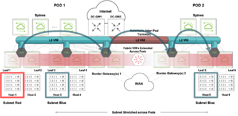
Figure 10-5: Local to Stretched Subnet Forwarding
As depicted in Figure 10-5 above, in this scenario when a packet from Host 1 needs to be routed to Host 5, it is rewritten with the destination address of Host 5 and then sent over a tunnel using subnet Blue’s L2 VNI from the ingress node’s VTEP to the local fabric’s Border Gateways 1. This is also referred to as the asymmetric routing model. Then, using the same L2 VNI, the packet is bridged over a different tunnel to redundant Border Gateways 2.
Lastly, when the packet reaches Border Gateways 2, the usual (and final) bridging step on subnet Blue is performed over a tunnel also using subnet Blue’s L2 VNI.
In the reverse direction a response from Host 5 to Host 1 would follow the packet flow described in Figure 10-4 (non-stretched case).
Since two extra hops (using border gateways) are introduced, the model is also called the two hop VXLAN forwarding model for EVPN multi-pod integrated routing and bridging scenarios.
In a scenario with three or more (N) pods, it’s possible for a subnet to be stretched only on two (or fewer than N) pods. So a stretched subnet can also be a remote subnet for at least one pod. When a host in that pod sends traffic to the remote stretched subnet, the destination border gateways in the remote pods may not have an adjacency resolved for the traffic destination. In such cases, as normal, the adjacency is resolved by the border gateways by broadcasting an ARP request throughout the stretched subnet (that is, across multiple pods) and by learning about the destination from the ARP response. Once a destination host is discovered through this mechanism, the packet flow is the same as in Figure 10-4.
About Border Gateway High Availability
Any leaf node within a fabric can be made a border gateway, as long as it has BGP connectivity to EVPN nodes outside of the fabric.
A border gateway acts as a proxy for all the VTEPs in the fabric. As seen in the previous sections, it translates Type 2, Type 3, Type 5 routes to and from the EVPN peers. That means, in Pluribus parlance, that a border gateway assumes ownership of the translated vPort, VTEP, VNI and prefix/VRF route information gleaned from the external messages.
There can be multiple border gateways in a fabric to act as redundant nodes to proxy all of the above information. However, to avoid conflicts, it’s important to keep sole ownership for that information within the fabric. For that purpose, a primary border gateway is elected.
From a control plane perspective, border gateway nodes in cluster pairs inherit the master or backup state from the VRRP interfaces configured for their VTEPs. A fabric node state change on the primary causes the secondary border node to become primary. Upon a border gateway state change triggered by a VRRP state change, the new primary node refreshes its routes without altering the BGP neighbor state.
Similarly, from a traffic forwarding perspective, VRRP is used for the selection of the master/backup roles and for the definition of a common virtual IP (VIP) address. BGP neighborship, instead, uses each node’s physical IP (PIP) address.
The elected primary border gateway is in charge of injecting vPort/VTEP/VNI information learned from its EVPN peers. It can also deactivate such information as a consequence of a remote configuration change.
The secondary node is fully active too. It can advertise local VTEP/VNI information as part of the proxying process toward the external EVPN nodes. What a secondary node cannot do, however, is to inject (or deactivate) external vPort information into the fabric. That’s reserved to the primary node, that is, to the sole owner of such translated/proxied information.
A secondary node also periodically monitors the primary node for any loss of connectivity or possible malfunction. If an issue is detected (for example, the primary border gateway goes offline unexpectedly), the secondary node takes over the role of primary node and maintains any learned vPort database information with its newly acquired ownership. This means that there is no disruption to already established tunnels and to the traffic that is traversing such tunnels to reach external VTEPs.
About the VXLAN Loopback Trunk with EVPN
VXLAN forwarding requires hardware functions like multiple lookups, encapsulation and decapsulation operations, packet replication, etc., even more so with EVPN’s two hop forwarding model. This can be implemented using the VXLAN loopback trunk (i.e., the default option).
Starting from release 6.0.0, Netvisor ONE supports single-pass VXLAN forwarding and flood as an alternative to using the VXLAN loopback trunk. With EVPN, customers using the VXLAN loopback trunk in prior releases can still use it for backward compatibility. On the other hand, single pass mode can be used on supported platforms for instance to optimize the two hop forwarding model on non-border gateway nodes.
Note: As of Netvisor ONE release 6.1.0, Dell S4100 and S5200 platforms can be used in single pass mode as non-border gateway nodes. Refer to the Configuring the VXLAN Loopback Trunk section in the Configuring VXLAN chapter for details on the configuration and platform support of single pass mode.
For nodes to be configured as border gateways and to use single pass forwarding, the node's hardware must be able to support both single pass mode and border gateway functions (for the latter refer to the platform list in the About EVPN Border Gateways section above).
About MAC Mobility with EVPN
A MAC address can be learned in one pod and then it can move to another pod, for example, when a virtual machine is migrated across locations. This is referred to as a ’MAC move’. Netvisor ONE supports the standard RFC 7432’s MAC Mobility Extended Community functionality to automatically deal with MAC moves between pods.
This specialized Extended Community is added by the EVPN control plane in MAC/IP Advertisement (i.e., Type 2) routes when a MAC move is detected. It comprises a list of fields, including flags and a sequence number. The sequence number is particularly important to ensure that border gateways retain the most recent MAC/IP Advertisement route when multiple updates occur for the same MAC address.
RFC 7432 also specifies how to deal with scenarios in which MAC moves are too frequent, for instance due to a mis-configuration. In these scenarios, it is possible that MAC address duplication occurs, and hence very frequent MAC moves are triggered for an extended period of time.
In order to perform MAC address duplicate detection per the RFC, the following configuration parameters are used in conjunction with a remediation action:
- Max moves (N MAC moves, with a default value of N = 5)
- Moves duration (M-second timer, with a default value of M = 180)
The RFC states that a node must start an M timer whenever it detects a MAC move: then, if it detects N MAC moves before the timer expires, it concludes that MAC address duplication has occurred. Consequently, the node must take a remediation action (such as alerting the operator) and must stop sending and processing any BGP MAC/IP Advertisement routes for that MAC address until a corrective action is taken.
As part of this corrective action, it’s possible to configure a third parameter to stop the MAC address flapping for a configurable period of time. This additional parameter defaults to 180 seconds and is called:
- Freeze duration
For more details on the configuration of the above parameters, refer to the configuration section below. (Instead, for intra-pod MAC move protection, refer to the Configuring Excessive MAC or IP Move Protection section of the Configuration Guide.)
About IGMP Snooping with EVPN
In case of an EVPN multi-pod network, basic IGMP Snooping support for VXLAN needs to be extended so that IGMP messages are propagated across pods. This is achieved as an extension of the local IGMP flooding process to forward the messages across the inter-pod automatic tunnels.
Whenever a multicast destination host sends an IGMP join or leave message for a multicast group, Netvisor ONE running on a border gateway notices that the message originated from within the pod and so floods it across the automatic tunnels between the local pod and the peer ones. Then, when the flooded IGMP message arrives at the neighbor border gateways, they in turn flood it to all the local VTEPs over the intra-pod tunnels. This results in the IGMP messages propagating to all the nodes, both intra- and inter-pod, within a flood domain. This allows the distributed control plane to learn about all the (local or remote) hosts that want to join or leave a multicast group.
As a consequence, L2 data plane forwarding rules are applied in hardware to known multicast traffic so as to limit head-end replication only to the inter-pod tunnels over which at least one remote host has indicated interest in a multicast group.