
Configuring VXLAN-based Bridge Domains for 802.1Q and QinQ Internetworking
Bridge domains’ configuration process is based upon the deployment of a VXLAN transport as described in the Configuring VXLAN chapter of this guide.
Subsequently, switch ports can be selectively added to a BD to accept either 802.1Q frames or double-tagged 802.1ad frames based on the connected device(s) and/or network(s), as depicted in the Figure 9-6.
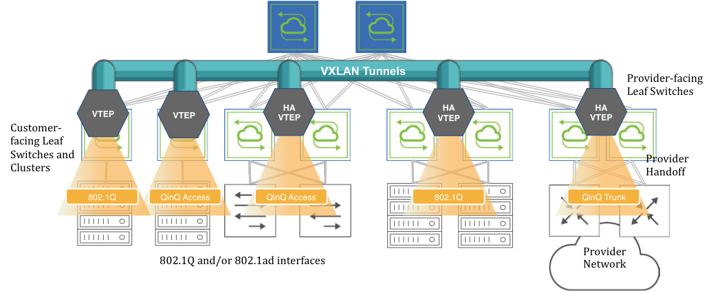
Figure 9-6: VXLAN-based BD Internetworking
Switch ports can be connected to either servers/hosts or switches/provider gateways as shown above.
In case of interconnection with an external cloud provider’s gateway devices, as shown on the right hand side of Figure 9-6, the connectivity is based on double-tagged 802.1ad frames, as it is required to preserve all 16M (4094 x 4094) possible combinations of user IDs and service IDs.
On the other hand, connectivity to servers can be based on a single 802.1Q VLAN tag. This case is useful in private cloud networks for direct server-to-server connectivity (for example a Web services node that needs to communicate with a database node).
Alternatively, server NICs can be configured with both an outer VLAN and an inner VLAN ID. In such case, the inner VLAN represents for example the service implemented on such server. Certain network designs employ this double-tagging scheme to be able to scale the number of supported services to 16M. In this case, switch ports have to be configured in 802.1ad mode to preserve the inner tag.
The 802.1Q ports can also be used to connect to customer switches and traffic can be double tagged by the fabric leaf nodes themselves.
Note: BD ports can be configured in 802.1Q mode or in 802.1ad/QinQ mode but not in both on the same switch for the same BD. Starting from NetVisor OS release 6.1.1, in remove-tags mode, this restriction has been lifted (see the following sections for more details).
Note: Starting from NetVisor OS release 7.0.1, it is possible to configure BD ports in 802.1Q mode and in 802.1ad/QinQ mode on the same switch.
Before adding ports to any of the aforementioned scenarios, the first basic configuration step is the creation of a VXLAN-based bridge domain entity with the command:
CLI (network-admin@leaf-5) > bridge-domain-create
|
bridge-domain-create |
Create a bridge domain. |
|
name name-string |
Specify the name for the bridge domain. |
|
scope local|cluster|fabric |
Specify the bridge domain scope. |
|
Specify any of the following options: |
|
|
vnet vnet-name |
Specify the vNET for this bridge domain. |
|
vxlan 0..16777215 |
Specify the VXLAN identifier for the tunnel. |
|
auto-vxlan|no-auto-vxlan |
Specify the options to automatically assign VXLAN and/or assign to VTEPs. |
|
description description-string |
Add a bridge domain description. |
|
rsvd-vlan 1..4093 |
Specify the fabric reserved VLAN for cluster switches for bridge domain. |
|
local-rsvd-vlan 1..4093 |
Specify the local reserved VLAN for cluster switches for bridge domain. |
|
mac-learning|no-mac-learning |
Specify if you want to enable or disable MAC address learning. |
CLI (network-admin@leaf-5) > bridge-domain-create name bd1000 scope fabric vxlan 10000 rsvd-vlan 4002
A bridge domain’s scope can be fabric, cluster, or local.
The bridge-domain-create command uses a manually assigned VNI to uniquely identify the bridge domain at the hardware level.
Moreover, with fabric and cluster scope, it must set aside a VLAN ID as reserved for supporting switch clusters:
CLI (network-admin@leaf-5) > bridge-domain-create name bd1000 scope fabric vxlan 10000 rsvd-vlan 4002
This command reserves VLAN 4002 on all cluster switches in the fabric for BD’s internal use, so it can no longer be configured as a regular VLAN number. (The same requirement applies to bridge-domain-create scope cluster commands).
If for a particular pair of cluster switches the reserved VLAN has to be modified, on any one of the two switches you can use the following command:
CLI (network-admin@leaf-5) > bridge-domain-modify name bd1000 local-rsvd-vlan 4006
Note that the above command requires both cluster switches to be rebooted to take effect. Before rebooting, both VLAN 4002 and 4006 are no longer available but only 4006 is reserved on the cluster switches after reboot.
Also note that in a cluster both switch members are required to use the same mode for a port, either QinQ or 802.1Q, for the same BD.
Bridge domains can also be created with a textual description to provide more context like so:
CLI (network-admin@leaf-5) > bridge-domain-create name bd1000 scope fabric vxlan 10000 description business rsvd-vlan 4002
CLI (network-admin@leaf-5) > bridge-domain-show
name scope vxlan auto-vxlan description ports cluster-name
------ ------ ----- ---------- ----------- ---- ------------
bd1000 fabric 10000 no business 13
Starting from NetVisor OS release 6.0.0 the auto-vxlan parameter is supported as an option of the BD creation process.
This new parameter can be used either in combination with an explicit VNI value or implicitly without specifying it. In both cases any created BD or VNI mapping is automatically added to all the existing VTEP connections. Additionally, in the latter case, the VNI value is automatically picked and assigned out of a predefined range (see also the examples below) when scope fabric is used.
The next configuration step is to set up the fabric overlay either with manual tunnel creation or with VTEP object configuration. The latter way is preferred.
In order to manually create a VXLAN tunnel, say, on cluster member leaf-5 in the Figure 9-6, the following commands can be used:
CLI (network-admin@leaf-5) > tunnel-create scope cluster name tunnel-5 vrouter-name vr5 peer-vrouter-name vr1 local-ip 20.20.25.1 remote-ip 20.20.27.1
CLI (network-admin@leaf-5) > trunk-modify name vxlan-loopback-trunk ports 17 jumbo
The same steps are required on the other leaf switches to deploy an overlay comprising a full mesh of VXLAN-based interconnections.
Alternatively, VTEP objects can be configured so that a full mesh of VXLAN interconnections is brought up automatically without requiring manual configuration.
This is the command required to create a VTEP object on a non-clustered switch:
CLI (network-admin@leaf-1) > vtep-create name vtep1 vrouter-name vr1 ip 20.20.25.1
which can be used to create each fabric termination point (vtep1, vtep2, etc. on each leaf switch).
In case of clustered switches using a common VIP, the following command pairs should be used:
CLI (network-admin@leaf-5) > vtep-create name vtep5 vrouter-name vr5 ip 103.103.103.250 virtual-ip 103.103.103.10
CLI (network-admin@leaf-6) > vtep-create name vtep6 vrouter-name vr6 ip 103.103.103.251 virtual-ip 103.103.103.10
The next configuration step is to associate the BD’s VXLAN ID (e.g., 10000) to the newly created tunnel(s) or VTEP objects. For example, this command implements the association with a tunnel:
CLI (network-admin@leaf-1) > tunnel-vxlan-add name tunnel-1 vxlan 10000
whereas this command implements the association with a VTEP object:
CLI (network-admin@leaf-1) > vtep-vxlan-add name vtep1 vxlan 10000
As mentioned above, starting from NetVisor OS release 6.0.0, as an alternative to the manual assignment, you can automatically assign a certain user-defined BD or VNI mapping to all tunnels with the following command:
CLI (network-admin@leaf-5) > bridge-domain-create name bd5001234 scope fabric vxlan 5001234 auto-vxlan
Instead, if you want the software to automatically pick and assign the VNI, you can simply enter the following shorter command that requires scope to be fabric:
CLI (network-admin@leaf-5) > bridge-domain-create name BD-VNI-SELF scope fabric auto-vxlan
The range used for automatic VNI assignment can be controlled and modified, if needed, with the vtep-auto-vxlan-show and vtep-auto-vxlan-modify commands.
Once the VXLAN overlay deployment is complete and the BD’s VXLAN ID is (manually or automatically) associated to it, then it is possible to start adding switch ports.
Informational note: Before NetVisor OS release 6.1.1., when a port is assigned to a BD (as in the examples below) it cannot be associated with a regular VLAN configured with the vlan-create command, and vice versa. The restriction has been lifted in release 6.1.1.
In order to add a port connected to the cloud provider network to the BD, you can use the following command that explicitly maps both inner and outer VLANs to the BD:
CLI (network-admin@leaf-7) > bridge-domain-port-add name bd1000 port 13 outer-vlan 13 inner-vlan 100
This configuration also means that a frame’s MAC lookup in the Layer 2 table is performed including both the outer VLAN and the inner VLAN.
The same configuration can be used to add a port connected to an 802.1ad-configured server to the BD:
CLI (network-admin@leaf-2) > bridge-domain-port-add name bd1000 port 11 outer-vlan 13 inner-vlan 100
In order to add a port connected to an 802.1Q network to the BD, you can use the following command that explicitly maps only the outer VLAN to the BD (and preserves the inner VLAN):
CLI (network-admin@leaf-2) > bridge-domain-port-add name bd1000 port 15 outer-vlan 19
This configuration also means that a frame’s MAC lookup in the Layer 2 table is performed including only the outer VLAN while the inner VLAN is ignored.
In order to add a port connected to an 802.1Q server to the BD, you can use the following command that explicitly associates one or more VLANs on the same switch port to the same BD:
CLI (network-admin@leaf-1) > bridge-domain-port-add name bd2100 port 10 vlans 210,310
Note: The multiple VLAN IDs on the same port can be part of the same bridge domain. However, VLAN IDs added to a BD cannot be reused with another BD on the same port. Also note that MAC addresses associated with these two VLAN IDs must be unique within the BD.
Finally, you should also configure all cluster ports/trunks and ports in QinQ mode to work with the 802.1ad TPID (i.e., 0x88A8) with the following command:
CLI (network-admin@switch) > port-config-modify port <port_number> allowed-tpid q-in-q
Port removal from a BD and BD deletion follow the reverse order compared to the addition process described in the above steps.
Ports have to be removed first with the command:
CLI (network-admin@leaf-2) > bridge-domain-port-remove name bd1000 port 15
Then a BD’s VXLAN ID may be manually removed from the associated tunnel(s):
CLI (network-admin@leaf-2) > tunnel-vxlan-remove name tunnel-2 vxlan 10000
or from the corresponding VTEP objects like so:
CLI (network-admin@leaf-2) > vtep-vxlan-remove name vtep2 vxlan 10000
Finally, the BD can be deleted with the following command:
CLI (network-admin@leaf-2) > bridge-domain-delete name bd1000
Starting from NetVisor OS release 6.0.0, when a BD is deleted, if it was previously created with the auto-vxlan option, the BD or VNI mapping gets removed from all the tunnels automatically, so you don’t need to do it manually.
From NetVisor OS version 6.1.0, the vxlan-stats-show command displays the statistics for VXLANs associated with bridge domains.
For example, to view the VXLAN statistics for the bridge domain BD100, use the following command:
CLI (network-admin@switch) > vxlan-stats-show bd BD100 layout vertical
time: 03:23:19
vnid: 12591499
vxlan-name:
vnet:
bd: BD100
ibytes: 7.60T
ibits: 66.8T
ipkts: 3.59G
idrops-pkts: 0
obytes: 7.54T
obits: 66.5T
opkts: 3.59G
odrops-pkts: 0
Configuring Outer TPID for Double-tagged Packets
By default a QinQ bridge domain port is configured to use the 802.1ad TPID (i.e., 0x88A8) in the outer tag.
Starting from NetVisor OS release 7.0.1 it is possible to configure the TPID to be 0x9100 or 0x8100, instead, to be compatible with other QinQ implementations (for example, Cisco Systems’ original QinQ).
On the NRU03, NRU-S0301, AS7726-32X/F9432-C, AS7326-56X/F9480-V, AS5835-54X/F9460-X, AS5835-54T/F9460-T platforms and on the Dell S5200 Series it is possible to configure the TPID on a per switch port basis, like so:
CLI (network-admin@switch) > port-tpid-modify ports <port-list> outer-tpid <tpid-value>
Possible TPID values are:
- dot1q (0x8100)
- q-in-q (0x88A8)
- q-in-q-old (0x9100)
- none (default)
When outer-tpid is configured as none (default), double tagged packets use the standard 802.1ad encapsulation with the outer TPID equal to 0x88A8 (and the inner TPID equal to 0x8100).
Here is an example of configuration of the TPID to be 0x9100:
CLI (network-admin@switch) > port-tpid-show ports 121,123,32
switch ports outer-tpid
------ ----- ----------
switch 121 q-in-q
switch 123 q-in-q
test4 32 q-in-q
CLI (network-admin@switch) > port-tpid-modify ports 123,121 outer-tpid q-in-q-old
CLI (network-admin@switch) > port-tpid-show ports 121,123,32
switch ports outer-tpid
------ ----- ----------
switch 121 q-in-q-old
switch 123 q-in-q-old
test4 32 q-in-q
On the other hand, on platforms that are not NRU03, NRU-S0301, AS7726-32X/F9432-C, AS7326-56X/F9480-V, AS5835-54X/F9460-X, AS5835-54T/F9460-T and the Dell S5200 Series it is possible to configure the TPID on a per bridge domain port basis like so:
CLI (network-admin@switch) > bridge-domain-port-add name <bd-name> port <port> outer-vlan <vlan-id> outer-tpid <tpid-value> [inner-vlan <vlan-id>]
For example:
CLI (network-admin@switch*) > bridge-domain-port-add name bd1 port 11 outer-vlan 2001 inner-vlan 201 outer-tpid q-in-q-old
CLI (network-admin@switch*) > bridge-domain-port-show
name port outer-vlan single-bum-domain vlans inner-vlan l2-learning outer-tpid
---- ---- ---------- ----------------- ----- ---------- ----------- ----------
bd1 11 2001 false 201 none q-in-q-old
Note: TPID configuration on a per bridge domain port basis is not supported for bridge domains when vxlan-inner-packet mode is set to transparent.
Configuring Bridge Domains in vNETs
NetVisor OS version 6.1.0 supports the configuration of bridge domains in vNETs. This enhancement enables vNET users to configure bridge domains on vNET ports so that they can be managed on a per tenant basis.
To configure bridge domains in a vNET, you should first specify the number of allowed bridge domains in the vNET when creating it. Also, you must specify the vlan-type as private, because the default vlan-type is public but bridge domains are supported only in global or private vNETs. For example:
CLI (network-admin@switch) vnet-create name vnet1 scope fabric vlan-type private vlans 300-400 num-bridge-domains 3 vxlans 10100 vxlan-end 10200
You can now create a bridge domain in vnet1 by using the command:
CLI (network-admin@switch) bridge-domain-create name bd1 scope fabric vxlan 10100 vnet vnet1
View the bridge domain configuration by using the command:
CLI (network-admin@switch) > bridge-domain-show layout vertical
name: bd1
vnet: vnet1
scope: fabric
vxlan: 10100
auto-vxlan: no
rsvd-vlan: 2833
vxlan-inner-packet: auto
qinq_rsvd_vlan: 2833
mac-learning: on
Note:You cannot specify a reserved VLAN for a bridge domain in a vNET configuration as the reserved VLAN is automatically selected from the vtep-auto-vlan range. Since this VLAN range is common to all vNETs, you cannot create bridge domains in a vNET if this pool is exhausted.
The vtep-auto-vlan range has 500 VLANs allocated by default:
CLI (network-admin@switch) > vtep-auto-vlan-show
vlans: 2500-2999
You can widen this range, for example, by 11 VLANs by using the command:
CLI (network-admin@switch) > vtep-auto-vlan-modify vlans 2500 vlan-end 3010
|
vtep-auto-vlan-modify |
Modify the VLAN ID range for automatic assignment to VTEPs at the fabric level. |
|
vlans 0..4095 |
Specify the starting VLAN ID for vtep-auto-vlan range. |
|
vlan-end 0..4095 |
Specify the ending VLAN ID for vtep-auto-vlan range. |
Note: The vtep-auto-vlan reserved range and the VLAN range manually allocated to each vNET must be mutually exclusive.
Add ports to bd1 by using the bridge-domain-port-add command:
CLI (network-admin@switch) > bridge-domain-port-add name bd1 port 33 vlans 100
Note: You can only add vNET managed ports to the bridge domain. However, there is no restriction on assigning VLANs that are not part of the vNET to the bridge domain.
View the configuration using the command:
CLI (network-admin@switch) > bridge-domain-port-show
switch name port vlans l2-learning
------ ---- ---- ------- -----------
switch bd1 33 100 none
To complete the configuration, as demonstrated earlier, associate the bridge domain's VXLAN ID with a tunnel by using the command:
CLI (network-admin@switch) > tunnel-vxlan-add name t1 vxlan 10100
You can also associate the bridge domain's VXLAN ID with a VTEP by using the vtep-vxlan-add command as shown earlier.
Configuring VLAN Ranges On Bridge Domain Ports
Starting from release 7.0.0 NetVisor OS supports the configuration of VLAN ranges on a bridge domain port.
A VLAN range can be used to minimize the amount of flooded (Broadcast/Unicast /Multicast, BUM in short) traffic that goes out of a bridge domain port: for each VLAN range only one copy of this kind of traffic is transmitted (instead of N copies, with N equal to the number of VLAN numbers in the range).
Referring to Figure 10-6 above, for example an 802.1Q BD port on a switch can send traffic to a QinQ BD port on a different switch (over the VXLAN transport): a QinQ BD port (with the outer-vlan parameter configured) and a BD port with a VLAN range can be configured across a VXLAN-tunnel to provide the desired end-to-end 802.1Q tunnel functionality.
NetVisor OS supports this feature on the following platforms:
- F9480-V (AS7326-56X), F9460-X (AS5835-54X), F9460-T (AS5835-54T)
- Dell S5200 Series
- NRU03, and NRU-S0301.
Note: This feature is supported only in auto BD mode.
Note: VLAN translation and the untagged-port-vlan configuration are not supported in conjunction with this feature.
A vlan-range corresponds to a compact grouping of VLAN numbers described by two values: the lowest and the highest number in the range. The command syntax is:
CLI (network-admin@switch) > bridge-domain-port-add name <name> port <port> vlan-range <range>
You can configure only one range on a port for a bridge domain (the maximum number is 8 ranges per port with different bridge domains; the limit is hardware dependent), as shown in this example:
CLI (network-admin@switch) > bridge-domain-port-add name test port 12 vlan-range 15-16
If you try to configure more than what the hardware supports, you will get an error message:
CLI (network-admin@switch) > bridge-domain-port-add name test port 12 vlan-range 12,14,15-16,20,23,25,27-29,30,32,35,38
bridge-domain-port-add: Too many ranges, limit to 1
A VLAN range can include all VLANs (1-4092) like so:
CLI (network-admin@switch) > bridge-domain-port-add name bd-1 port 10 vlan-range all
CLI (network-admin@switch) > bridge-domain-port-show
switch name port vlans single-bum-domain l2-learning
------ ---- ---- ------ ----------------- -----------
switch bd-1 10 1-4092 true none
On the other hand, a traditional range can be created by using this syntax:
CLI (network-admin@switch) > bridge-domain-port-add name bd-1 port 12 vlans 10-12
In this case, three copies of any flooded traffic with three VLAN numbers (10, 11 and 12) will be generated by the hardware.
You can distinguish traditional ranges from vlan-range groupings in the bridge-domain-port-show output by looking at the single-bum-domain column: when it’s true, it’s a vlan-range:
CLI (network-admin@DUT) > bridge-domain-port-show
switch name port vlans single-bum-domain l2-learning
------ ---- ---- ----- ----------------- -----------
switch bd-1 10 10-12 true none
switch bd-1 12 10-12 false none
Note: You cannot change a vlan-range with the bridge-domain-port-modify command: you need to delete the port first and then re-add it with the new vlan-range.
Note: To work on clusters the vlan-range feature requires the cluster over Layer 3 feature to be enabled. Refer to the Configuring High Availability chapter for more details.