MST - Config
Layer 2 Configuration – MST (Multiple Spanning Tree) Configuration
Multiple Spanning Tree Protocol, as defined in IEEE802.1s or IEEE802.1Q-2005, provides the ability to manage multiple VLANs using Multiple Spanning Tree Instances (MSTIs). MSTP allows the formation of MST regions that can run multiple MSTIs. MSTP regions and other STP bridges are interconnected using the Common and Internal Spanning Tree (CIST).
We define MSTP regions as a collection of switches with the same VLANs configured on all of them. All switches in a region must have the same configuration name, revision level, VLANs, and VLAN to MSTI associations. Each MST region may have multiple MSTIs operating within it, but an MSTI cannot span multiple regions. Each MSTI must have a regional root, which it may or may not share with another MSTI.
The CIST is the default spanning-tree instance in MSTP. CIST forms a larger spanning tree for the entire bridged network by combining MSTP regions and single-instance spanning trees.
The CIST instance has an MSTI ID of 0, which cannot be deleted or changed. When creating a new port-based or tagged VLAN, it is associated with the CIST by default and automatically assigned an MSTI ID of 0. The default VLAN on a switch is also associated with the CIST.
When giving a VLAN to an MSTI, it partially remains a CIST member because CIST is used by MSTP to enable communication with MSTP regions and RSTP/STP single-instances in the network. CIST also has regional roots.
The switch with the lowest CIST priority value functions as the root bridge for all the MSTP regions and STP/ RSTP single-instance spanning trees in the network.
There are features and functions used in UNUM Manager and UNUM Analytics that are common throughout the user interface (UI). Please refer to the Common Functions section for more information on the use of these functions and features.
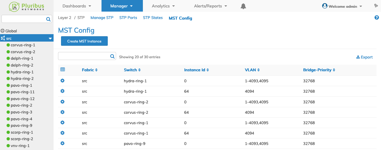
Selecting Manager → Layer 2 → MST displays the MST dashboard with a list of any existing entries.
Select the applicable Fabric from the left-hand navigation bar and the dashboard updates showing all MST entries from all switches within the Fabric.
Note: If no entries exist a "No Data Exists" message is displayed. You must first configure an entry on a switch. Prerequisite settings and configuration may be required.
The dashboard displays a list of existing MST entries by Fabric.
Additional parameters include: Switch, Instance Id, VLAN, and Bridge Priority.

Manager MST Config Fabric Dashboard
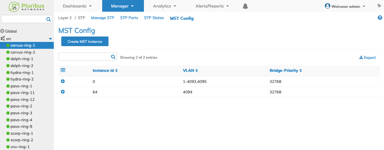
Selecting an individual Switch from the fabric updates the dashboard with only the MST settings for that switch.
The dashboard displays a list of existing MST entries. Additional parameters include: Instance Id, VLAN, and Bridge Priority.
Note: MST must be enabled each switch otherwise it will not update in the dashboard and an error message displays.

Manager MST Config Switch Dashboard
Create MST Instance
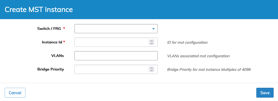
To create an MST instance, select Create MST Instance and enter the required parameters, which include:
•Switch / FRG – (drop-down) - Select All, a switch or FRG (Fabric Resource Group).
•Instance Id – ID for mst configuration.
•VLANs – Vlans associated mst configuration.
•Bridge Priority – Bridge Priority for mst instance - Multiples of 4096.

Manager MST Config Create an MST
Click Save to continue or Cancel to return to the previous screen without making any changes.
Edit MST Configuration
To edit an entry, select Edit using the Cog ![]() icon and enter the required parameters, which include:
icon and enter the required parameters, which include:
•VLANs – Vlans associated mst configuration.
•Bridge Priority – Bridge Priority for mst instance - Multiples of 4096.

Manager MST Config Edit an MST
Click Save to continue or Cancel to return to the previous screen without making any changes.
Delete MST Entry
To delete an entry, select Delete using the Cog ![]() icon.
icon.

Manager MST Config Delete an MST Entry
Click OK to continue or Cancel to return to the previous screen without making any changes.
