
Launch Playbook
Launch Playbook
Click Launch Playbook to select the applicable configuration playbook.
Click Next to continue.
Each Playbook will contain specific configuration parameters which you will need to provide.
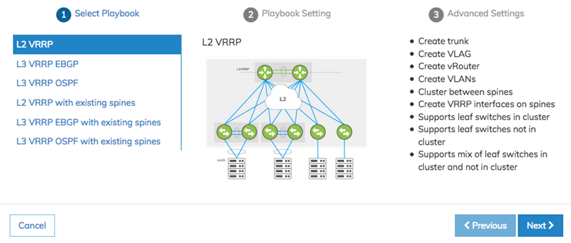
NetVisor UNUM Platform Global - Add Fabric Select Playbook
Example of L2 VRRP configuration screens.
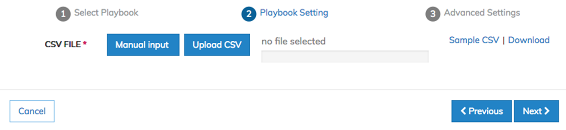
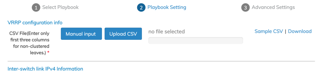
NetVisor UNUM Platform Global - Add Fabric Playbook Setting
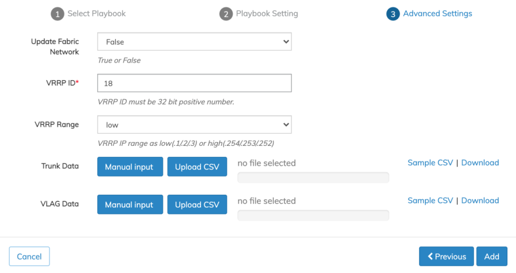
Sample CSV files are available for download for each Playbook.
You manually enter configuration settings or upload a CSV file using Manual Input or Upload CSV.
A sample CSV file is available for download by selecting Sample CSV | Download.
During manual input of ZTP VRRP configurations, you select from a list of switches from the drop-down menu.
The drop-down menu lists all switches in the Fabric, however in specific cases, not all switches are applicable.
Please follow the Playbook guidelines listed below:
•The L2 VRRP Playbook supports VRRP between spines only.
•The L3 BGP and L3 OSPF Playbooks support VRRP between leafs only.
•The L2 VRRP 3rd Party Spines Playbook, neither are supported.
•The L3 BGP and L3 OSPF 3rd Party Spines Playbook supports leafs only.
Manual Input

NetVisor UNUM Platform Global - Add Fabric Playbook Setting Manual Input
Click Add+ to enter your configuration parameters.
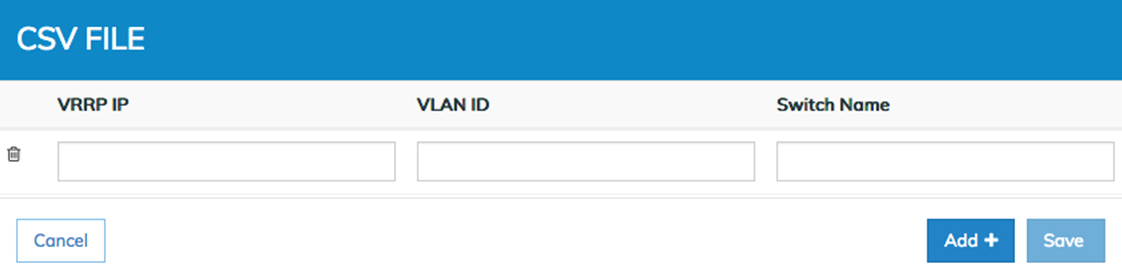
NetVisor UNUM Platform Global - Add Fabric Manual Input Parameters
Enter the IP address with a valid CIDR subnet mask for the VRRP, the ID number for the VLAN and the Switch Name.
Click Add+ to enter additional configuration parameters until your configuration is complete. Remove entries using the Trash ![]() icon.
icon.
Click Save to continue.
Host Facing VLAGs
NetVisor UNUM version 6.3.0 supports creating host-facingVLAGs in the L2/L3 Fabric Playbooks using CSV files and the NetVisor UNUM interface.
The virtual chassis logical model can be effectively used to enable an advanced capability called multi-chassis link bundling/port channeling. This feature is also known as MC-LAG (Multi-Chassis Link Aggregation Group). An MC-LAG is a cross-device link bundle (i.e., Trunk). It typically has at least one port member on one switch and another port member on a backup switch. It can be facing downstream toward an endpoint (configured with a regular LAG on its end) or upstream toward another switch or router (also using a regular LAG or even an MC-LAG).
Arista Networks’ implementation of MCLAG is called VLAG (Virtual Link Aggregation Group) on a switch cluster. That, in practice, means in order to be able to configure a VLAG, first set up a cluster pair.
The cluster trunk is just a regular LAG but is the pivot around which various important functions revolve. First off, it provides a critical communication channel utilized for cluster synchronization activities and protocol exchanges. It is also instrumental for supporting the MC-LAG (a.k.a. VLAG) function on the cluster, as it can function as a backup forwarding path during failover scenarios. From a high-level perspective, a VLAG is a single logical but physically redundant upstream or downstream connection across a pair of cluster switches. In other words, physically, it’s a triangular topology that includes the cluster trunk, while logically, it appears just as if it were a point-to-point multi-link connection.
For instance, using clusters with VLAGs is a technique often chosen to avoid using the Spanning Tree Protocol (STP) for Layer 2 redundancy.
This property makes active-active VLAGs ideal for many Layer 2 or Layer 3 network designs.

VLAG Cluster Example
Furthermore, using the same approach allows for the interconnecting of dual-homed servers to leaf switches.

VLAG Example - Multi-Chassis
Playbook Support
Trunk and VLAG functionality apply to the following Playbooks:
•L2 VRRP
•L2 VRRP Third-party
•L3 EBGP/OSPF
•L3 Third-party EBGP/OSPF
Create Trunks andVLAGs running on the host-facing ports on the leaf switches.
Creating Trunks is only possible if the number of ports connected to a host is more than one. Otherwise, leave the entry blank.
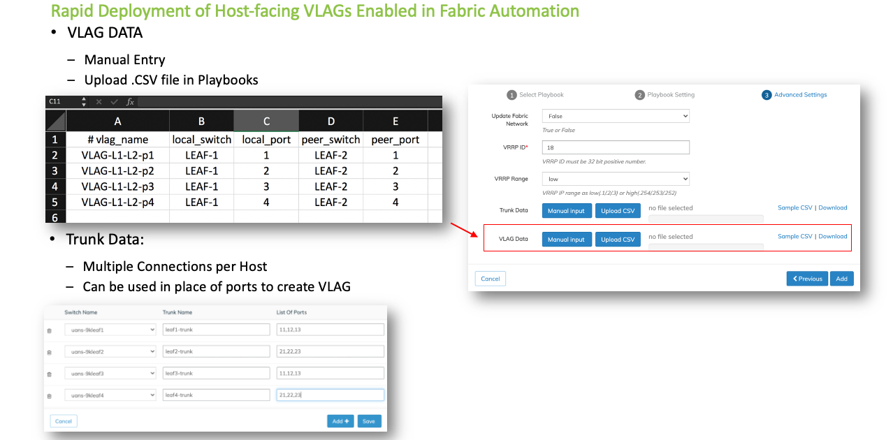
Use the following CSV file format to create a Trunk:
# switch_name, trunk_name, list_of_ports
Parameters:
•switch_name - the switch used to create the Trunk.
•trunk_name - the name used for trunk creation.
•list_of_ports - the ports separated by comma connected to the host.
The CSV file format for vlag creation is:
# vlag_name, local_switch, local_port, peer_switch, peer_port
Parameters:
•vlag_name - the name used in the vlag creation.
•local_switch - local VLAG switch.
•local_port - local VLAG port or, if it is multiple ports, then the trunk name used in the previous trunk CSV file.
•peer_switch - the VLAG peer switch.
•peer_port - VLAG peer-port or, if it is multiple ports, then the Trunk created on the peer switch.
Auto-Configuration of VLAGS in Automation Playbooks
Auto-Configuration of VLAGs in Automation Playbooks
Enter the required parameters in the CSV and Upload the CSV file.
Conversely, select Manual Input to enter the values via the UI directly.
NetVisor UNUM Platform Global -Trunk and VLAG Data CSV / Manual
Create a simple VLAG using either single physical ports across a cluster for a single connection. For more complex topologies or when using multiple links, you must use a set of trunks employing multiple ports across the cluster.

NetVisor UNUM Platform Global -Trunk and VLAG Ports Connection Examples
Once entered, the Trunk and VLAG entries appear in the dashboard as illustrated in the following examples.
Trunk

NetVisor UNUM Platform Global -Trunk Entries
Manually add more switches using the Add+ button. Remove entries using the Trash ![]() icon.
icon.
Click Save to continue.
VLAG
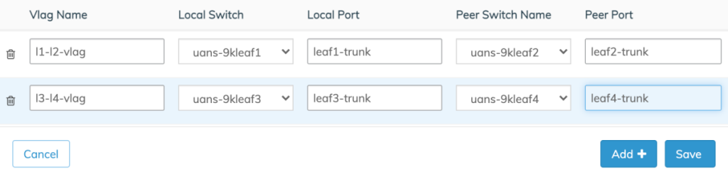
NetVisor UNUM Platform Global -VLAG Entries
Manually add more switches using the Add+ button. Remove entries using the Trash ![]() icon.
icon.
Click Save to continue.
Advanced Settings
Use the Advanced Settings menu to configure VRRP ID and VRRP Range.
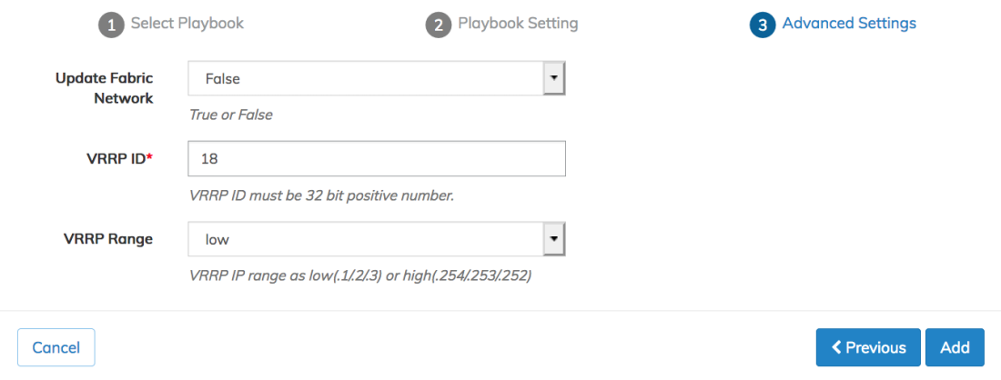
Click Add to continue, Previous to return to the Playbook Settings or Cancel to exit without making any changes.
Note: The VRRP virtual IP address can either be an x.x.x.1 with a master router of x.x.x.2 and an alternate of x.x.x.3, or x.x.x.254 with a master router of x.x.x.253 and an alternate of x.x.x.253. Administrators should choose the high or low option based on their fabric requirements.
Create Tunnels using L3 EBGP/OSPF & L3 Third-party EBGP/OSPF on Non-Clustered Leafs
After executing the initial Fabric, launch the L3 Playbook to configure eBGP or OSPF configuration.
In the following example, Leaf3 and Leaf4 are non-clustered.
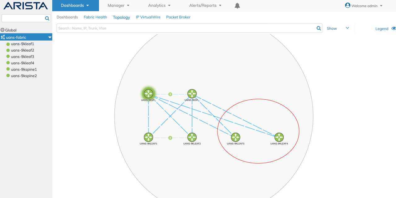
Non-Clustered Leafs Example
The VRRP CSV file input for non-clustered leafs are:
#vlan-id,vrrp-ip,switch_name1
For clustered leaves:
#vlan-id,vrrp-ip,switch_name1,switch_name2,vrrp-id,active_switch
The following is an example of a sample VRRP CSV file for a Fabric with both clustered and non-clustered leaves:
100,10.16.100.1/24,uans-9kleaf1,uans-9kleaf2,18,uans-9kleaf1
102,10.16.102.1/24,uans-9kleaf3
103,10.16.103.1/24,uans-9kleaf4
In the image above image, Leaf1 and Leaf2 are the clustered leaf pair. Leaf3 and Leaf4 are the non-clustered leaves in the fabric.
Select either Manual Input or Upload CSV (CSV file must contain the requisite values).
Non-Clustered Leafs Manual or CSV Selection
L3 EBGP & L3 OSPF Trunk Modify - VXLAN Loopback
NetVisor UNUM 6.3.1 supports a trunk modifying task in the L3 EBGP/OSPF Playbooks for the vxlan-loopback-trunk setting by adding ports to the VXLAN loopback trunk if not previously assigned, as shown in the following example.
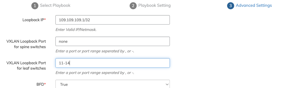
L3 EBGP & L3 OSPF Trunk Modify
Manual Input
Enter the values manually. The first three columns: VLAN ID, VRRP IP, and Switch Name are required entries. For non-clustered leafs only enter values in these columns.
Click Save to continue.
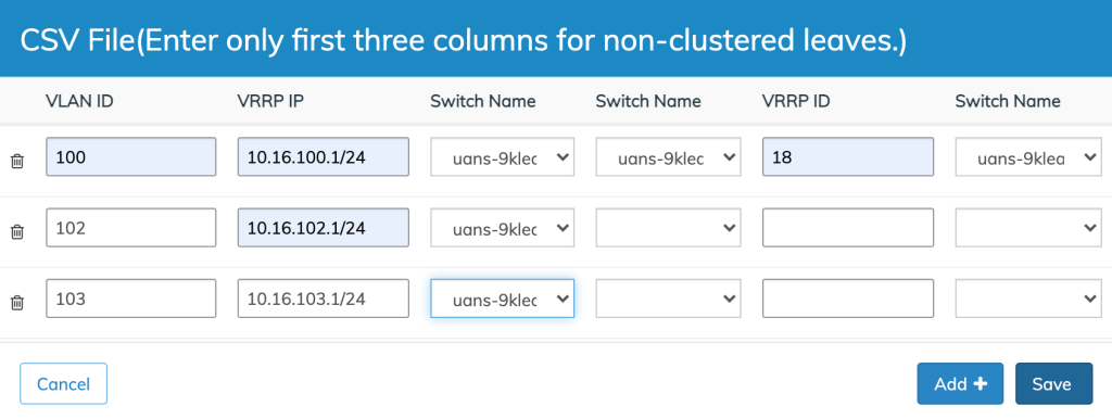
Non-Clustered Leafs Manual Data Input
Playbook Execution
When the Playbook configuration parameters are correctly entered click Add + and the Playbook execution begins.
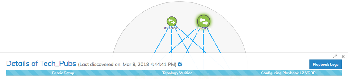
NetVisor UNUM Platform Global - Playbook Running
Various messages may appear during the Playbook execution and icons animations will appear on the dashboard indicating progress with the Playbook configuration.
Once the Playbook scenario has been successfully deployed you will see the following message:
NetVisor UNUM Platform Global - Playbook Successfully Deployed
Click Close to complete the configuration.