
System Interface
Medium Capacity Appliance - System Interface
Dell VEP4600 System Overview
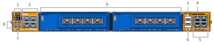
I/O Panel View
I/O Panel View
1.Platform status Icons LEDs
2.RS-232 console ports (top) and 10/100/1000 Base-T ports (bottom)
3.SFP+ ports
4.Luggage tag
5.1000Base-T networking ports
6.Processor power on/off button
7.Micro USB-B port
8.USB Type A ports
9.Optional - VEP4600 Expansion Cards
10.Power Supplies
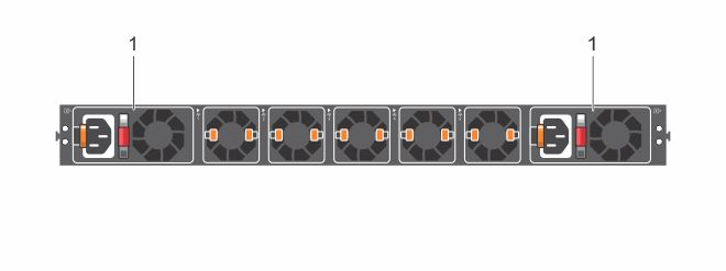
Power Supply (PSU) View
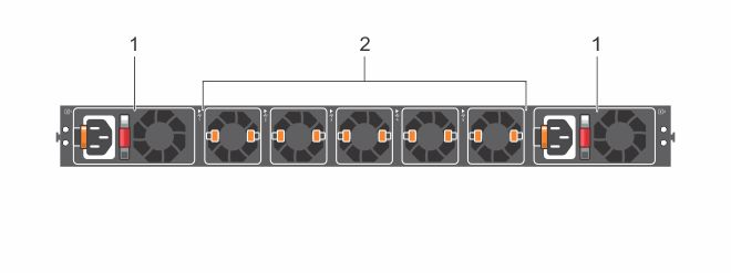
Power Supply View
1.PSUs
2.Fans
PSU LEDs
Power Supply LEDs
•Solid green—Input is OK.
•Flashing yellow (amber)—There is a fault with the PSU.
•Flashing green blink at 1Hz—Platform is in a standby/CR state.
•Off—PSU is off.
Control Panel LEDs
There are several LEDs on the control panel and on the drive carriers to keep you constantly informed of the overall status of the system.
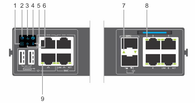
Control Panel LEDs
1.Power LED
2.Master LED
3.System LED
4.Locator LED
5.Temperature LED
6.Fan LED
7.SFP+ indicator LED
8.10/100/1000 BaseT RJ-45 networking link (left) and activity (right) LEDs
9.10/100/1000 BaseT RJ-45 networking link (left) and activity (right) LEDs for the processor (left) and for the BMC (right)
LED Behavior
|
LED |
Description |
|
System Status/Health LED |
•Off - system off or in standby •Solid green—Normal operation •Flashing green—Booting •Solid yellow (amber)—Critical system error or CPU power off. •Flashing yellow—Noncritical system error, fan failure, or power supply failure |
|
Power LED |
•Off - system off or in standby •Solid Green—Normal operation •Solid yellow—POST is in process •Flashing yellow—Power supply failed |
|
Master LED |
•Solid green—platform is in stacking Master or Stand alone mode •Off - system is slave of the stack or system in standby |
|
FAN LED |
•Off - system off or in standby •Solid green—Normal operation; fan powered and running at the expected RPM •Solid yellow—Fan failed |
|
PSU LED |
•Off—No power •Solid green—Normal operation or standby mode •Solid yellow—Power supply critical event causing a shutdown •Flashing yellow—PSU warning event; power continues to operate |
|
LOCATOR LED/System Beacon |
•Off—Locator function disabled •FFlashing blue with 1 sec on and 1 sec off – Locator function enabled •Flashing blue with 2 sec on and 1 sec off – system in standby |
|
Temperature status LED |
•Off - system off or in standby •Solid green—temperature is normal •Solid yellow—temperature is at the limit •Flashing yellow—temperature is over the limit |
|
RJ-45 Ethernet LED |
•Off—no link and no activity detected •On—Activity on the port •Solid yellow—Link operating at a lower speed •Solid green—Link operating at a maximum speed—1G •Flashing green—Port activity |
System Management Ethernet Port LEDs
|
Link LED |
•Off—No link •Solid green—Link operating at a maximum speed, auto-negotiated/forced or 1G •Solid yellow—Link operating at a lower speed, auto-negotiated/forced or 10/100M |
|
Activity LED |
•Off—No link •Flashing green—Port activity |
SFP+ Port LEDs
|
Link/Activity LED |
•Off—No link •Solid green—Link operating at maximum speed, 10G •Solid yellow—Link operating at a lower speed, 1G •Flashing green—port activity for 10G •Flashing yellow—port activity for 1G |
Luggage Tag
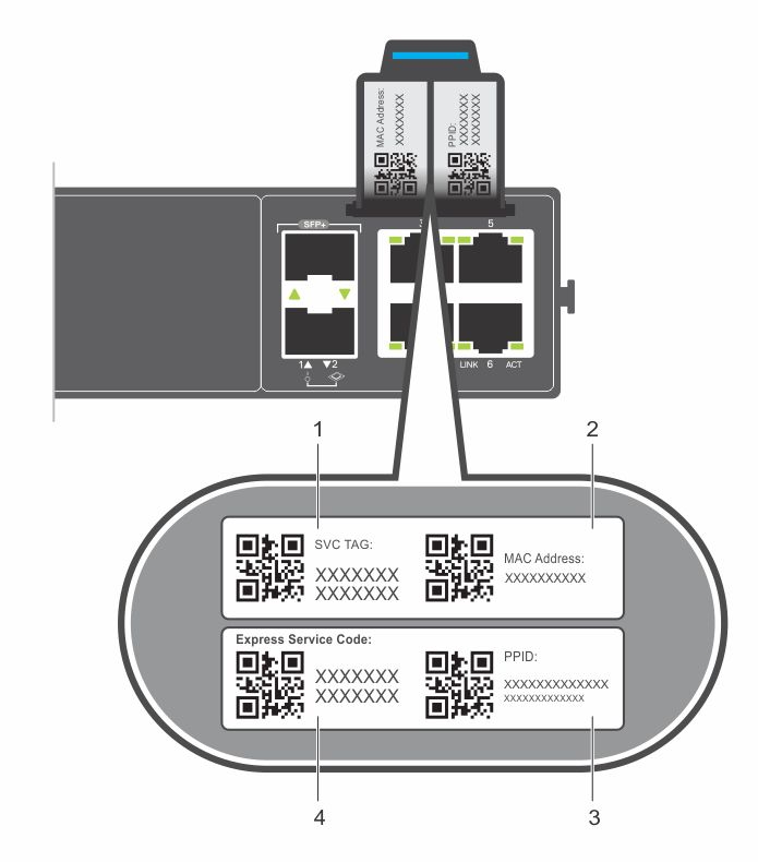
Luggage Tag
1.SVC tag
2.MAC address
3.PPID
4.Express service code
Management Ports
Management Ports
RS-232 Console Port Access
1.RS-232: processor console port (left); BMC console port (right)
Caution: Ensure that any equipment attached to the serial port can support the required 115200 baud rate.
Note: Before starting this procedure, ensure that your PC has a 9-pin serial port and that you have installed a terminal emulation program on the PC.
Note: If your PC’s serial port cannot accept a female DB-9 connector, use a DB-9 male-to-male adapter.
1.Install the provided RJ-45 connector-side of the provided cable into the platform console port.
2.Install the DB-9 female-side of the provided copper cable into your PC’s serial port. Or install the DB-9 cable into other data terminal equipment (DTE) server hardware.
3.Keep the default terminal settings on the console as follows:
•115200 baud rate
•No parity
•8 data bits
•1 stop bit
•No flow control
MicroUSB-B Console Port Access
The MicroUSB-B console port is on the PSU side of the VEP4600.
The terminal settings are the same for the serial console port and the RS-232/RJ-45 console port:
•115200 baud rate
•No parity
•8 data bits
•1 stop bit
•No flow control
When you connect the microUSB-B port, it becomes the primary connection and, while connected, all messages are sent to the microUSB-B port.
Note: Before starting this procedure, be sure that you have a terminal emulation program already installed on your PC. Install the appropriate drivers to support the microUSB-B port. To download Dell EMC drivers, see https://www.dell.com/support. If your computer requires non-Dell EMC drivers, contact Dell EMC Technical Support for assistance.
1.Power on the PC.
2.Connect the USB-A end of cable into an available USB port on the PC.
3.Connect the microUSB-B end of cable into the microUSB-B console port on the platform.
4.Power on the platform.
5.Install the necessary USB device drivers.
6.To download Dell EMC drivers, see https://www.dell.com/support. If your computer requires non-Dell EMC drivers, contact Dell EMC Technical Support for assistance.
7.Open your terminal software emulation program to access the platform.
8.Confirm that the terminal settings on your terminal software emulation program are as follows:
•115200 baud rate
•No parity
•8 data bits
•1 stop bit
•No flow control