Understanding Switch Clusters
In general, in computer science the term cluster (also known as high-availability/HA cluster or fail-over cluster) is used to identify a group of devices that are functionally equivalent and structurally redundant so that they are able to provide continuity of service (without user intervention) when any component or an entire device fails. Therefore they are used for critical applications when all single points of failure must be eliminated.
Pluribus Networks builds upon this concept to bring end-to-end multi-pathing with advanced redundancy to high-performance networks where HA is a critical requirement, especially in case of mission-critical high-uptime data center and enterprise deployments.
For this reason Pluribus’ clustering technology represents a key pillar of Pluribus’ Adaptive Cloud Fabric architecture as well as a powerful tool for network designers. From a practical standpoint it allows customers to deploy in many critical points of the network redundant pairs of switches (simply referred to as switch clusters or clusters) with both upstream and downstream traffic load balancing and fast failover capabilities.
A common scenario is depicted in Figure 7-3 below.
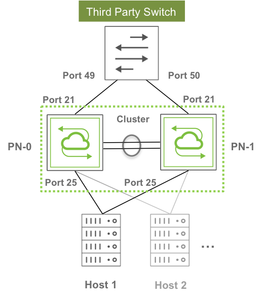
Figure 7-3 - Example of Requirement for Upstream and Downstream Path Redundancy
As seen in the figure above, clusters can interconnect third-party switches as well as servers in a redundant fashion simply by using standard technologies (link bundling or NIC bonding) on those devices.
The key is that each redundant pair of Pluribus switches functions as a single logical entity capable of inter-switch state synchronization to guarantee proper Layer 2 operation as well as traffic load balancing and failover. To external devices this switch pair appears as a single virtual neighbor both for traffic forwarding and for protocol communication purposes.
As a matter of fact, in computer networking an alternate name that is sometimes used for a cluster is virtual chassis. And this latter designation is perhaps more useful to describe the concept: a pair of separate physical switches is joined in a virtual entity that behaves as if ports belonging to each device were unified within a common virtual chassis.
In Pluribus’ advanced networking architecture clustering is a natural fit and represents a logical extension of the fabric. The requirement for clustering is in fact that the two switches be members of the same fabric instance.
In addition, due to the asymmetric nature of certain interactions, when you create a cluster you must designate one cluster node as cluster-node-1 (that is, primary node) and the other as cluster-node-2 (that is, secondary node).
In order to set up a cluster, an active link between the primary and the secondary node must exist (as shown above in Figure 3). This is called a “cluster link” and can comprise one or more ports directly connecting the two cluster nodes together. If there are more than one port, they will be automatically bundled and the cluster link will effectively be a “cluster trunk” (that is, the LAG of those ports).
Using an intrinsically redundant cluster trunk for cluster node interconnection is the recommended best practice.
The aggregate bandwidth of such trunk should be such that no major traffic bottleneck is experienced in case of failover scenario and/or in the presence of single-homed upstream or downstream devices (while in the former case the cluster trunk is used as backup path only in case of failure, in the latter case a portion of the traffic is always forced to cross the cluster links). This bandwidth calculation varies depending on the network design, the traffic type, the number and requirements of the single-homed devices, etc.
VLAN 4094 is reserved and is used to carry cluster synchronization traffic. It is automatically added to the in-band interface port and to the cluster link when you create the cluster configuration. This is possible because Netvisor ONE detects cluster links using an extra data set sent in LLDP messages. Therefore, when a cluster link is detected through this mechanism, VLAN 4094 is automatically added to it.
Netvisor ONE performs cluster synchronization over the control network of the fabric. For the in-band interface, synchronization uses VLAN 4094 over the cluster links. For management, synchronization is performed over the management interface.
Each cluster node sends a synchronization message (with cluster state, versioning info, device uptime, etc.) to the peer node every 2 seconds. These messages function also as keepalives: so if three messages in a row are missed, the cluster pair goes offline (that is, symmetrically).
On the other hand, the process of going online for the cluster happens asymmetrically, for two main reasons: to avoid race conditions and to determine an additional important state of each node, the master or slave role, for protocol support purposes. Synchronization messages are thus exchanged and used to select the master and slave roles via an internal negotiation algorithm based on parameters like uptime.
When a cluster comes online, it triggers:
- A resend of all status updates to the peer node
- A re-synchronization of all vLAGs
- The transition of STP to run in cluster mode
Synchronization of vLAGs (see also the next sections) is used to make sure that they behave as a single logical entity across both nodes. This is achieved by synchronizing port state, as well as Layer 2 entries when needed.
vLAGs in a cluster can work in active-standby mode (where only the vLAG members on one node are active) or in active-active mode (where all the vLAG members are active and forwarding). The latter mode requires Layer 2 entry/vPort synchronization across nodes.
vLAG state synchronization typically happens from the primary node to the secondary node. However, the secondary node can synchronize a (local) port state when that port comes up. In case of necessity it can also request the primary node to (re)start the synchronization process.
Layer 2 entry synchronization is instead performed symmetrically by both nodes upon detection of a vPort change for performance reasons.
About the Cluster Re-peer Process
When a cluster node dies or needs replacement, it is necessary to use another switch to substitute the failed/missing node to rebuild the cluster pair as soon as possible so as to restore network redundancy.
Initially, the cluster-repeer command was used to rebuild a cluster with a new switch node. Subsequently, as an enhancement, the rebuild process was integrated into the fabric join procedure. A cluster pair is now restored via the fabric-join command followed by the option:
repeer-to-cluster-node |
Replace a dead cluster node by restoring against the existing cluster node. |
Before adding a new cluster node, though, the node to be replaced must first be evicted from the fabric with the fabric-node-evict command.
Then, in order to be able to rebuild a cluster via the fabric-join command with the repeer-to-cluster-node option, the new node needs to be directly connected to the remaining cluster node that is still active.
The joining node that performs a fabric-join to repeer with the cluster’s master node will initiate direct communication with it to get up-to-date fabric and cluster configuration files and transaction IDs.
After the joining node installs the new configuration, it transmits a fabric-join transaction to notify all fabric members that it has joined the fabric. In addition, it runs a cluster-update command which rebuilds the cluster pair with itself and the existing cluster peer as members. The existing cluster peer will also modify any cluster objects that may require an update as a consequence of the repeer procedure (for example, trunks).
Finally, the joining node restarts and the process is complete.
The aforementioned procedure implicitly applies to Layer 2-based fabric topologies where direct Layer 2 connectivity with the other fabric nodes is possible for message exchange.
In case of Layer 3 fabric designs, instead, a further enhancement has been introduced in Netvisor ONE release 5.1.0 to perform the repeer operation over a Layer 3 fabric interconnect.
A new fabric-join option has been added to allow the users to specify that a cluster pair needs to be rebuilt over a Layer 3 fabric configuration:
over-l3 |
Specify to establish fabric is over layer 3. |
In addition, a new over-l3 flag has been added to the output of the fabric-info command to indicate whether it’s a Layer 2 or Layer 3 case.