Example: Configuring a Swich for VirtualWire™ Mode
The configuration example in this section refers to a VirtualWire fabric composed by one spine and two leaf switches as in the figure below.
Two devices, device-A and device-B, have respectively two ports and one port that are physically connected to the VirtualWire switch Leaf-1. A third device, device-C, is physically connected to the VirtualWire switch Leaf-2.
The desired logical setup consists in a bidirectional service chain topology where device-A is inserted in-line between device-B and device-C.
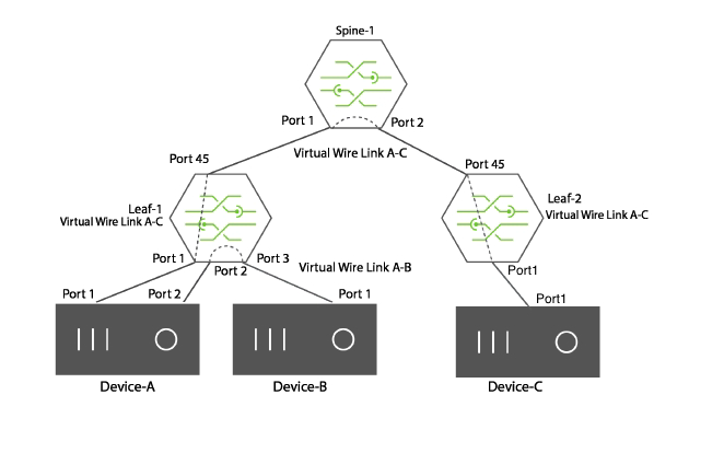
Figure 1-11 - Bidirectional Traffic over a VirtualWire Connection
To create a bidirectional virtual link from device-A to device-C, use these steps:
1) Configure a port association for device-A to device-C using port 1 and port 45 on Leaf-1.
CLI (network-admin@Leaf-1) > port-association-create name link-AC virtual-wire bidir master-ports 1 slave-ports 45
2) Configure a port association on Spine-1 between ports 1 and 2:
CLI (network-admin@Spine-1) > port-association-create name link-AC virtual-wire bidir master-ports 1 slave-ports 2
3) Configure a port association on Leaf-2 between ports 45 and 1:
CLI (network-admin@Leaf-2) > port-association-create name link-AC virtual-wire bidir master-ports 45 slave-ports 1