Overview
Pluribus Networks Adaptive Cloud Fabric Overview
Pluribus Networks’ Adaptive Cloud Fabric is deployed in two different ways, using the out-of-band management network or using the in-band network (bridged or routed network). Both options have pros and cons, and the decision to deploy one model or another really depends on the network constraints and the use case.
The following section describes the two typical fabric architectures you can create, with or without Virtual Netvisor deployed and added to the fabric.
Management Fabric
A Management fabric uses the out-of-band management network to send fabric messages and form a fabric. The following diagram shows the route used by fabric messages in a management fabric using out-of-band ports on Pluribus Networks switches:
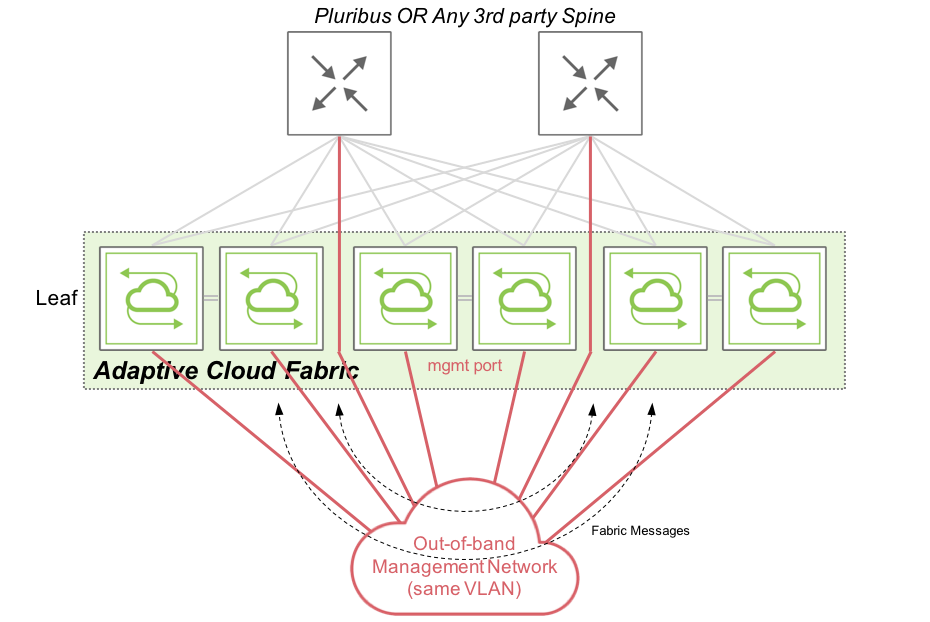
Figure 1 - Management Fabric Communications
Netvisor sends and receives fabric messages, essentially keepalive and configuration messages, over the out-of-band network which are consumed by other fabric nodes. These messages ensure each and every node within a fabric, along with other fabric nodes, can initiate/receive a configuration instruction to/from other nodes.
Inband Fabric
An in-band fabric uses the in-band network to send fabric messages and form the fabric. Netvisor provides two options for the in-band network forming the network:
- The underlay network is a Layer 2 network (using Pluribus Networks clusters and VLAGs for redundancy):
A VLAN to transport fabric messages across the L2 network, similarly to what is performed with a management fabric but using an in-band VLAN (VLAN 1 being the default VLAN used for the fabric).
- The underlay network is a Layer 3 network (using IGP and ECMP for redundancy):
The local in-band (fabric) subnet, unique per fabric node, advertises to other nodes using the underlay routing protocol. Once IP connectivity is established between Pluribus Networks switches, they can join the same fabric and exchange fabric messages over this routed network.
Note: Although an in-band fabric is supported using a Layer 2 or Layer 3 underlay network, Pluribus Networks strongly recommends implementing a Fabric over a Layer 3 network when configuring an in-band fabric, as Netvisor extends the fabric to a remote site.
The following diagram shows the path taken by fabric messages in an in-band fabric using a Layer 3 underlay network on Pluribus Networks switches:
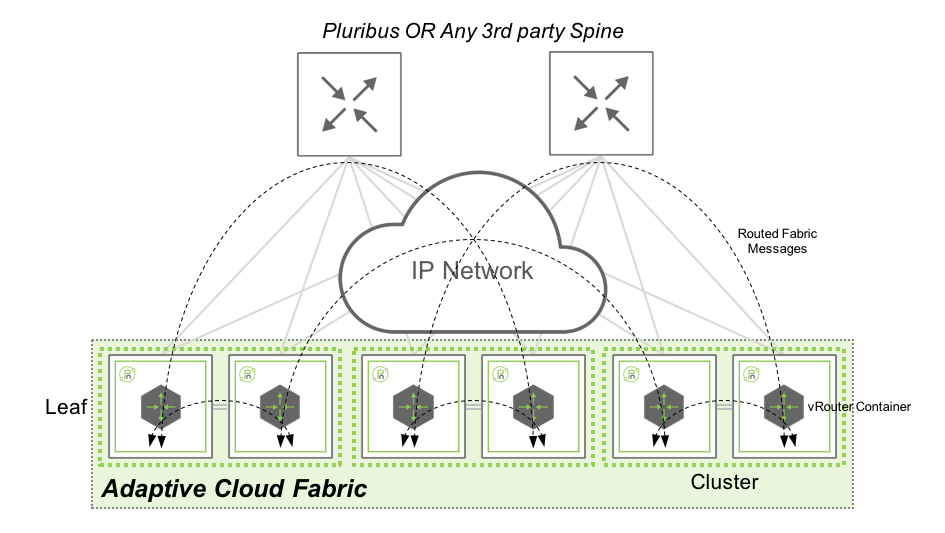
Figure 2 - In-band Fabric Communications with Layer 3 Underlay Network
Netvisor sends and receives fabric message over in-band network, by using the local vRouter and consumed by other fabric nodes. In this architecture, Fabric messages are routed from one switch to another using the IGP (BGP, OSPF or Static) configured by the network administrator. This design gives the flexibility to extend a fabric from a local site to geographically dispersed locations, as it relies on standard routing protocols with no specific requirements on latency, jitter or MTU.
Virtual Netvisor (vNV) Overview
Netvisor provides Virtual Netvisor as a virtual edition of Pluribus Networks Netvisor and provides a partial set of features like a regular physical switch.
The form factor of Virtual Netvisor is a Virtual Machine running a base Linux OS (Ubuntu) and Pluribus Networks Netvisor on top to bring a data center class network feature set.
Another Fabric Node
Virtual Netvisor is running Netvisor like a regular node, consequently, it is another fabric node participating in the distributed management and control plane. Despite a limited set of functionalities available in Virtual Netvisor (no L2 functions for instance), we use this node as part of an existing node composed of physical switches to provide a powerful compute fabric node for compute intensive control plane activities.
Creating Containerized Network Functions such as vNET Manager or OVSDB Server which consume a tremendous amount of CPU/Memory resources make vNV ideal when used in a pure compute instance.
When Virtual Netvisor joins an existing fabric with physical nodes, it receives and processes all fabric transactions like a regular node.
Software Architecture
The following figure shows an overview of vNV software architecture:
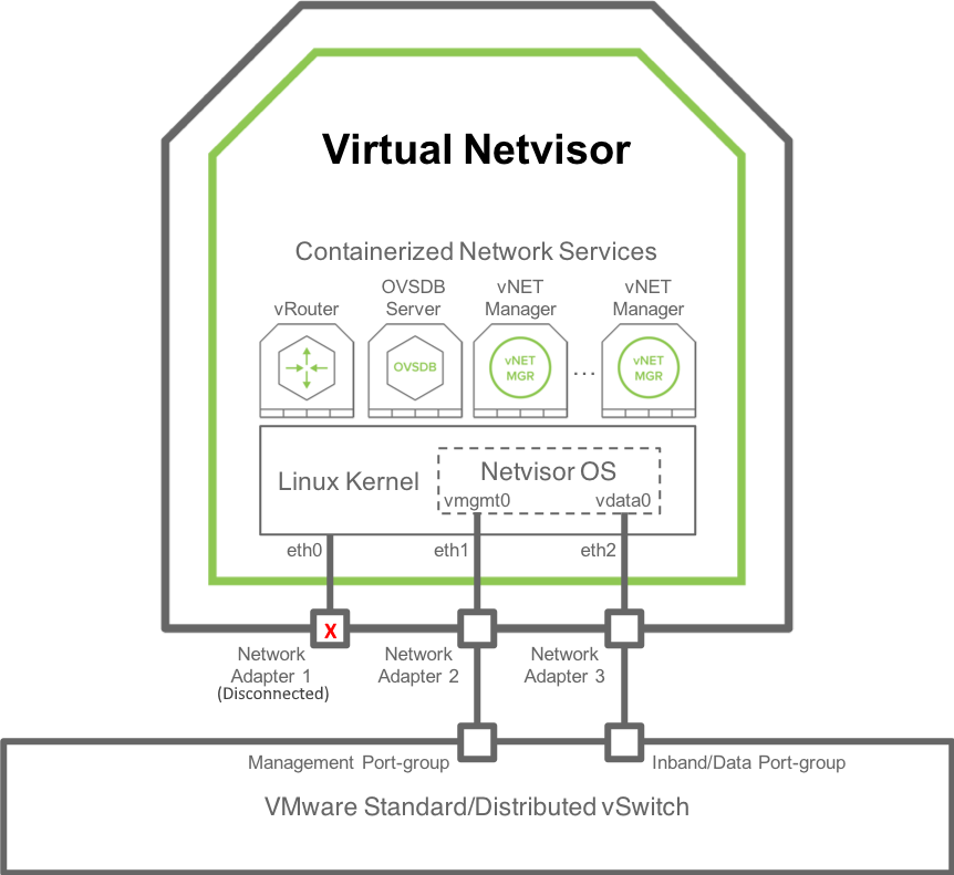
Figure 3 - vNV Software Architecture
vNV is a Virtual Machine with the following components:
- Linux OS (current 5.1.0 release uses Ubuntu 16.04 with a Linux Kernel 4.15).
- 3 Kernel network interfaces:
- eth0: not used. This is “Network Adapter 1” in the VM configuration in VMware vSphere Web Client.
- eth1: used by Netvisor for the management port/interface. This is “Network Adapter 2” in the VM configuration in VMware vSphere Web Client.
- eth2: used by Netvisor for the data/in-band port/interface. This is “Network Adapter 3” in the VM configuration in VMware vSphere Web Client.
- 2 OVS bridges (not represented in this diagram) connecting Netvisor to the Linux Kernel (see OpenVSwitch documentation for more details):
- Management bridge (called nvm-mgmt-br).
- In-band bridge (called nvm-data-br).
- Netvisor running as a daemon in the Host Kernel space (nvOSd) and using the following interfaces:
- vmgmt0: connected through Management OVS bridge to eth1 interface in the Linux Kernel. This is the Netvisor Management port/interface seen in the CLI/API.
- vdata0: connected through in-band OVS bridge to eth2 interface in the Linux Kernel. This is the Netvisor In-band/Data port/interface seen in the CLI/API.
- Linux Containers to host Network services such as:
- A vRouter: provides L3 connectivity and dynamic L3 control plane (for dynamic routing).
- An OVSDB Server: exposes an OVSDB interface to 3rd party SDN controller.
- vNET Managers: provides a fully isolated management view for each tenant admin in the context of a multitenancy fabric architecture.
Joining a Fabric with vNV
Virtual Netvisor (vNV) is a regular Netvisor node and hence requires to be connected to the same management or in-band network to join an existing fabric.
As vNV is a Virtual Machine (VM), the way you can connect it to the network is slightly different from a physical switch.
This section describes the supported topologies to deploy vNV and join an existing fabric of physical switches.
Management Fabric
Flat Management Domain
Using the management network, vNV is installed and deployed in the following topology:
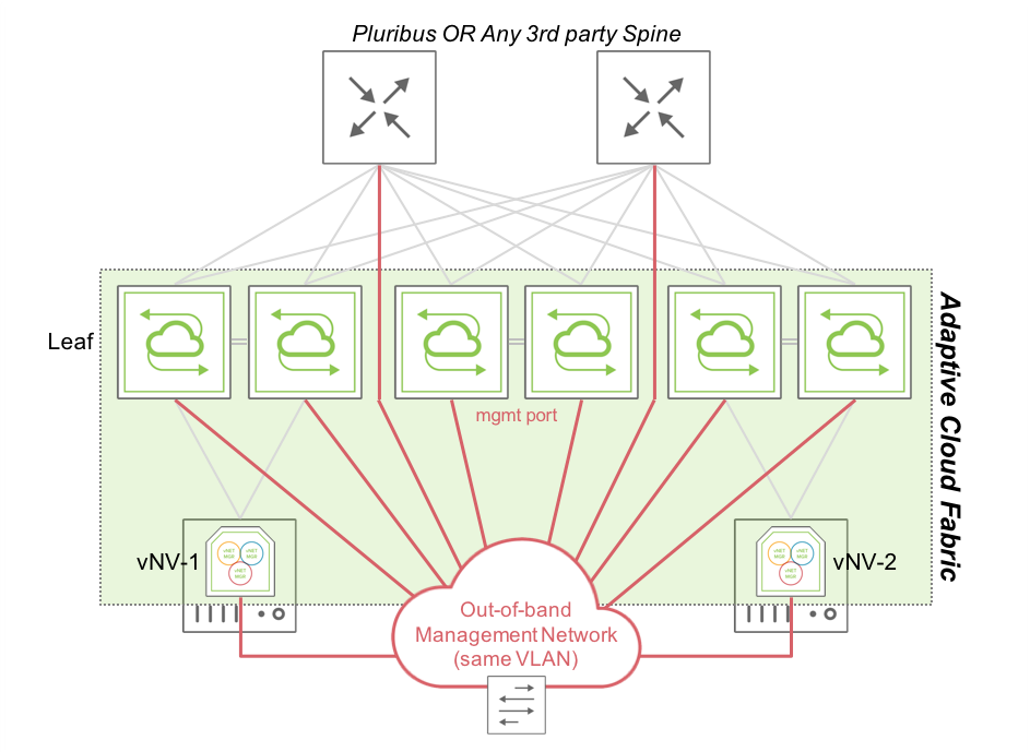
Figure 4 - Fabric Nodes in a “Flat” Management Network
In this topology, two vNVs deployed in two VMware ESXi servers are connected to two different clusters of Pluribus Networks switches or to the same cluster.
vNV-1 and vNV-2 use only their Management interface to communicate with the rest of the fabric, as they are not expected to forward any in-band traffic. Instead, they provide more power to the fabric and perform compute intensive tasks which some white box switches cannot handle without degrading performances in the network.
Routed Management Domain
In certain cases, it might be complicated to connect ESXi hypervisors in the out-of-band network directly (in the same VLAN or bridge domain):
- Servers with a limited number of interfaces.
- Physical restrictions.
- Security restrictions.
In this case, create a Management fabric using an IP network to connect fabric nodes together. The only requirement is IP reachability between fabric nodes.
The following diagram is an example of a Management fabric where physical switches are connected to the Red Management network and ESXi servers are connected to another Blue Management network. If these two networks are routed between each other, vNVs join the existing Management fabric formed by physical switches.
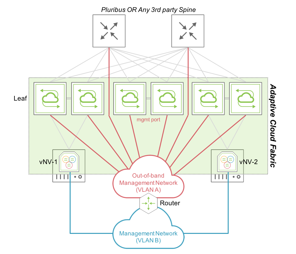
Figure 5 - Fabric Nodes in a Routed Management Network
In this topology, vNV-1 and vNV-2 use only their Management interface to communicate with the rest of the fabric and fabric messages are routed to communicate with other nodes part of the same fabric, as opposed to the previous topology where all nodes were sitting in the same broadcast domain.
In-band Fabric Using VRRP
Using the in-band network with a Layer 3 underlay network, vNV is installed and deployed in the following topology:
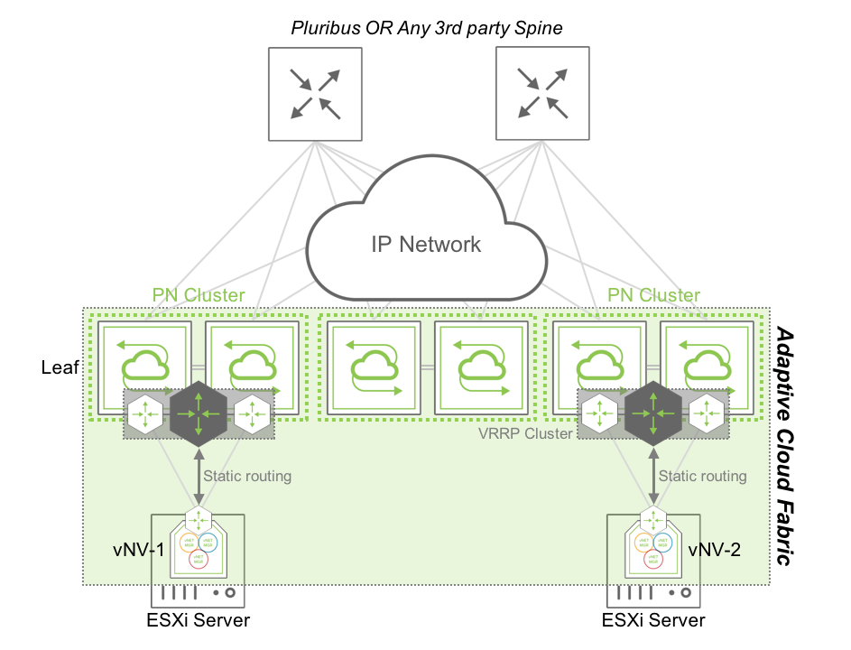
Figure 6 - Fabric Nodes in a Routed In-band Network using VRRP
In this topology, two vNVs are deployed in two VMware ESXi servers, connected to two different clusters of Pluribus Networks switches or to the same cluster.
vNV-1 and vNV-2 use their in-band interface to communicate with the rest of the fabric and use the top of the rack (ToR) switches to communicate with other nodes. The two ToR switches are configured in a VRRP cluster and redistribute this local subnet in the IGP to advertise it to other fabric nodes. Each vNV have a default route pointing to this VRRP Virtual IP (VIP) and communicate with any other nodes’ in-band interface in the network.
This option is the easy way to setup a hybrid fabric (physical + virtual) leveraging the underlay Layer 3 network.
In-band Fabric Using IGP
In certain cases, it is useful to run an IGP between vNV instances and the fabric nodes to provide a fully dynamic layer 3 architecture without relying on First Hop Redundancy Protocols (like VRRP, HSRP, GLBP, etc.).
Although there are no restrictions on where to run the IGP between vNVs and the physical switches, Pluribus Networks recommends running this IGP at the ToR. When vNV is running on ESXi servers and these servers are directly connected to the ToR switches to avoid implementing multi-hop routing protocols between vNVs and the Spine switches, Pluribus Networks recommends creating a L3 IGP adjacency with the first ToR switches.
Following that recommendation, vNV is installed and deployed in the following topology:
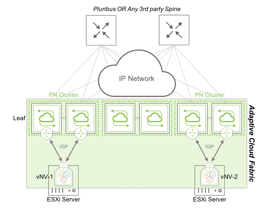
Figure 7 - Fabric Nodes in a Routed In-band Network using an IGP
In this topology, two vNVs are deployed in two VMware ESXi servers, connected to two different clusters of Pluribus Networks switches or to the same cluster.
vNV-1 and vNV-2 use their in-band interface to communicate with the rest of the fabric and use the top of the rack (ToR) switches to communicate with other nodes.
The two ToR switches are configured to form an IGP adjacency with the local vNV, with the same configuration which would be applied for any other L3 node in the fabric (there’s no difference because it is a Virtual Machine). The two vNV instances are configured with two different VLANs to connect to the ToR switches (one for each) and form an OSPF adjacency or BGP peering with the local ToR switches.
A simple network advertisement in the routing protocol (or connected routes redistribution) advertises vNVs’ local in-band interface to the rest of the network, ensuring fabric messages are delivered across the L3 network to other nodes.
Virtual Network (vNET) Overview
A Virtual POD (vPOD) is a logical construct in a shared infrastructure where a tenant can only see and use resources which are allocated to this tenant. A vPOD is composed of compute, storage and network resources and is created at the orchestration layer.
In a Pluribus Networks’ Adaptive Cloud Fabric, a vPOD translates to a Virtual Network (vNET), a collection of isolated network resources and services (defined by the Fabric administrator) associated with an independent management domain, allowing each vNET administrator to manage his/her own zone/environment.
Virtual Networks (vNETs) is Pluribus Networks’ advanced solution to dealing with multi-tenancy requirements in a secure and versatile manner that goes beyond basic VLAN and VRF standards. In basic terms vNETs are separate resource management spaces and operate in the data plane as well as in the control plane.
vNET Architecture
By creating a vNET in the Adaptive Cloud Fabric, the network resources are partitioned and dedicated to a single tenant with fully delegated management capabilities (optional). This partition of the fabric is configured either on one switch, a cluster of two switches, or the entire fabric by leveraging the “scope”, depending on where this vNET is required to deliver an isolated service to a tenant.
The figure below shows how a Multitenant leaf-spine design is achieved with a Pluribus Networks’ Adaptive Cloud Fabric:
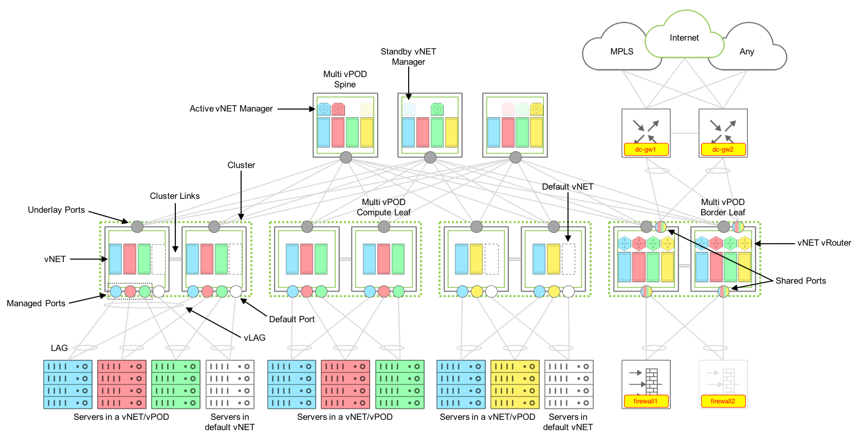
Figure 8 - Multitenant Fabric Design Components
Components
A multitenant fabric is built with the following components:
Default vNET
The Default vNET is the default partition on a switch used when the switch has not been configured with additional vNETs. This default partition “owns” all the resources on a Netvisor switch:
- Physical Ports.
- Default VLAN space.
- Default Routing table/domain (if enabled on the switch).
- The VTEP function.
- Any L2/L3 entries learned through static and dynamic protocols.
- Any additional container created.
The default vNET is not configured by the fabric administrator, it is a partition created as soon as the switch becomes part of a fabric. There is no vNET Manager container associated to the default vNET (see below for the description of a vNET Manager).
The default vNET has the following naming convention: [Fabric Name]-global.
Tenant vNET
A Tenant vNET is a partition which carves out the software and the hardware resources from the switch such as:
- VLAN IDs.
- MAC addresses.
- vRouter or VRFs.
- Remote VTEPs (Virtual Tunnel End Points).
- Physical ports.
A vNET is created with different scopes:
- Local: locally created on the switch and not usable by any other switch in the same fabric.
- Cluster: created on a cluster pair which share the same Layer 2 domain.
- Fabric: partition created on all switches in the same fabric.
Once a vNET is created, resources are associated to it when new objects are created in the fabric (VLANs, vRouters, etc.).
Although a vNET could be compared to a VRF, it goes beyond the VRF capabilities as it not only provides an isolated L3 domain, but it also offers the capability to have VLAN and MAC overlapping between vNETs. In other words, it is a complete isolation of the data plane and control plane, along with the management plane if there is a vNET Manager associated to it (see below for the description of a vNET Manager).
Each vNET has a single point of management. As the fabric administrator, one can create vNET and assign ownership of each vNET to individuals with responsibility for managing those resources and with separate usernames and passwords for each vNET managed.
There are two types of vNETs a Fabric Administrator can create, a Public vNET and a Private vNET:
Public vNET
A Public vNET is using the default 4K VLAN space available on a switch. In this case, the default vNET and any other vNET created share the 4094 VLAN IDs available on the platform with no option to have overlapping between VLAN IDs across vNETs.
By default, a vNET is created as Public vNET, although with Overlay networks and Multitenancy requirements, it makes more sense now to use Private vNETs almost exclusively.
Private vNET
A Private vNET is using an independent 4K VLAN space, where the vNET Administrator can create any VLAN ID he wants, regardless of whether that ID is used in the default vNET or in another Tenant vNET.
As the hardware architecture on Open Networking platforms does not offer unlimited resources, tables between the default vNET and any other vNET created still must be shared. Pluribus Networks provides a way to limit the amount of VLANs which are created in a Private vNET to avoid a situation where a tenant creating too many VLANs prevents other tenants to create VLANs as there are no hardware resources available on the switches.
To create this independent 4K VLAN ID space for each tenant, a mapping between two different types of VLANs is required, Public VLANs and Private VLANs, called vNET VLANs.
vNET VLANS
Public VLAN
A Public VLAN is a VLAN which uses the default VLAN ID space on a switch. When a Fabric administrator creates a VLAN on any Netvisor switch, without any vNET implemented (only the default vNET), it consumes VLAN IDs in the Public VLAN space.
Private VLAN
A Private VLAN is a user-defined VLAN ID in a private space, which has nothing to do with the actual VLAN ID (in the public space) used on the switch to learn L2 entries for this bridge domain. When the switch receives a frame with an 802.1q tag using the Private VLAN ID, it translates this VLAN ID to an internal VLAN ID in the 4K Public VLAN space.
When a Private VLAN must be transported over a VXLAN infrastructure, it requires a VNI to be associated to it so it is identified as unique in the shared (or public) Layer 2 domain.
The following diagram depicts the relationship between Public and Private VLANs in a Private vNET implementation:
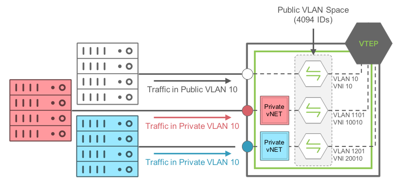
Figure 9 - Private VLAN-to-Public VLAN Mapping with Private vNETs
In this example, traffic coming on a Managed port from the RED Private vNET, using Private VLAN ID 10, is mapped internally to the Public VLAN ID 1101.
The same thing happens to traffic coming on a Managed port in the BLUE Private vNET, using Private VLAN ID 10 as well, it is mapped internally to the Public VLAN ID 1201.
The mapping is done automatically in Netvisor by defining a pool of usable Public VLAN IDs for Private vNETs.
Note: traffic from the RED Private VLAN 10 and BLUE Private VLAN 10 are NOT bridged at all as they are not in the same bridge domain internally.
Finally, traffic coming on a port on the default vNET, using VLAN 10 (so Public VLAN 10), is mapped internally to the same Public VLAN 10.
vNET Ports
Along with the VLAN and MAC table isolation, a complete isolation for each tenant at the physical port level is also required. To achieve this isolation at the access ports, the Adaptive Cloud Fabric introduces different types of ports to address different scenarios in a shared network.
Managed Port
A Managed port is an access port which is associated to one tenant only. This port is dedicated to a vNET and cannot be shared with other vNETs configured on the same switch. It is typically used to connect, and isolate resources dedicated to a tenant (like servers or any resource which is not an active L2 node).
Note: As an access port, a Managed port does not support Spanning-Tree. L2 loop prevention mechanism is implemented through another software feature called Block-Loops.
A Managed port is configured as an “access port” or a “Dot1q Trunk port”, if the VLANs carried on the port are part of the same Private vNET. It transports only Private VLANs belonging to the same vNET. It also supports Link Aggregation (802.3ad) on a single switch or with two different switches part of the same cluster (called Virtual LAG (vLAG) with Pluribus Networks switches).
Shared Port
A Shared port is an access port which can serve different tenants on the same port where a shared resource is connected. This port is not dedicated to a vNET and is shared with other vNETs configured on the same switch. It is typically used to connect shared resources like Gateways, Firewalls or even hypervisors hosting several VMs servers from different tenants.
A Shared port is always configured as a “Dot1q Trunk port” transporting Public VLANs only, from the same vNET or different vNETs on the same port. It also supports Link Aggregation (802.3ad) on a single switch or with two different switches part of the same cluster (called Virtual LAG (vLAG) with Pluribus Networks switches).
Underlay Port
In a vNET design, the underlay network topology is shared by all vNETs configured in the fabric. To avoid dedicating one Underlay port per tenant to connect Leaf switches to Spine switches, Pluribus Networks has abstracted Underlay ports from the vNET to leave their management to the Fabric administrator.
Underlay ports are the ports which interconnect Spine and Leaf switches or two switches part of the same availability Cluster. These ports are not configurable from the Private vNETs and are configured automatically based on the underlay design defined by the Fabric administrator.
vNET Manager
A vNET Manager is a container created on a fabric node and associated to a vNET to provide a dedicated management portal for the vNET. A vNET Manager is a completely stateless object, but it is deployed in high-availability mode to ensure the tenant never loses management access to the vNET. A vNET Manager in high-availability mode can have two different states:
- Active vNET Manager: elected container to manage resources allocated to a vNET. This container is the one used by the vNET Administrator to configure resources via CLI or API allocated by the Fabric administrator to this vNET.
- Standby vNET Manager: container in standby mode, sharing the same IP address with the Active vNET Manager container to offer high availability when the Active container fails or becomes inaccessible.
A vNET Manager is not mandatory to create a vNET, it is just providing a dedicated management portal to the tenant.
A vNET Manager container is an object local to the switch where it is created. In other words when the Fabric Administrator creates a vNET with a fabric scope, the vNET Manager associated to this vNET, is only created on the switch where the command is instantiated.
A vNET Manager is created on any switch in a fabric, if local resources (compute, memory and storage) are available.
vNET vRouter
A vNET vRouter is a network service container which provides L3 services with dynamic routing control plane to a vNET. A vNET is created:
- Without a vRouter container (L2-only vNET).
- With one single vRouter (L3 vNET).
- With more than one vRouter (Multi-VRF model in a vNET).
The first vRouter associated to a vNET builds the vNET (default) routing table. In some designs, a vNET can require more than one vRouter to support multiple routing tables, this is achieved by creating additional vRouter containers associated to the same vNET.
Unlike in a traditional multi-VRF router, multiple vRouter containers ensures a complete isolation between routing instances, within the same vNET, with a real resources isolation between routing domains.
In the future, each vRouter will extend to support multi-VRF to help maximizing the scale of VRFs without depending on resource-consuming vRouter containers.
A vRouter in a vNET supports the same feature set a vRouter created in the default vNET.
vNET Administrator
A vNET administrator (called vNET-admin) account is created when a vNET Manager container is created. This account has full read/write access to its associated vNET.
A vNET-admin account can only access his own vNET Manager and can only see resources belonging to its vNET. He’s responsible for the creation/deletion of the following:
- vNET VLANs/VNIs.
- LAGs/vLAGs for Managed ports associated to the vNET.
- vNET vRouters.
- VXLAN Tunnels for the vNET.
- L3 routing protocols for the vNET.
Fabric Administrator
The Fabric administrator (called fabric-admin) is the root account equivalent on a Linux distribution. It has all privileges to create, modify or delete any resource created on any fabric node. Besides having the same privileges that a vNET-admin has, the Fabric-admin can also manage the following fabric attributes:
- Fabric nodes.
- Clusters.
- vNETs.
- All Ports.
- VTEPs.
- vFlows (Security/QoS).
- Software upgrades.
vNET Manager High Availability
When deploying vNV to provide vNET Manager, you have two options to secure the management instance of the vNET:
- On a Single Site using VRRP between vNET Managers.
- On Multiple Sites with two independent instances of vNET Managers.
Single Site
When deploying vNVs in one single site, having Layer 2 domains across switches or racks is common, either through standard VLANs and VLAGs or through VXLANs and tunnels.
In this configuration, you can easily create 2 vNVs sharing the same broadcast domain and run VRRP protocol on their vNET Manager Interface.
Using VRRP between 2 vNVs offers the following benefits:
- One single IP to manage a vNET (easier to map one IP to DNS entries).
- Redundancy is offered by the protocol itself.
- Active/Standby model.
The following diagram shows how we can easily provide HA between vNVs when they are deployed on two servers sitting in the same rack:
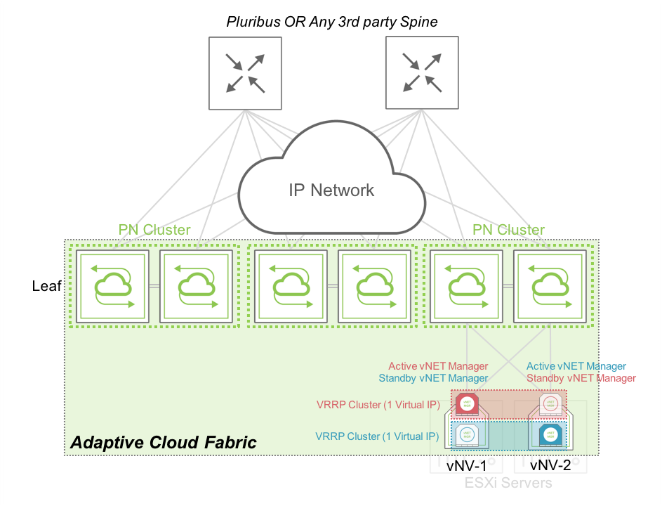
Figure 10 - vNET Manager Redundancy – Active/Standby in a Rack
In this case, both vNVs can exchange VRRP messages locally through the cluster of PN switches at the top of the rack. The vNET administrator has one single IP address to use to connect to his vNET. In case of failure or maintenance of one of the vNV instance, the same IP address is active on the remaining node.
The following diagram shows how we can provide HA between vNVs when they are deployed on two servers sitting in two different racks/clusters and connected through VXLAN tunnels:
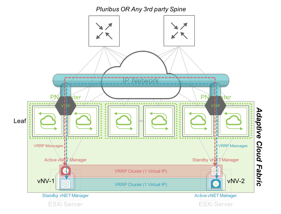
Figure 11 - vNET Manager Redundancy – Active/Standby between Racks
In this case, both vNVs can exchange VRRP messages through the VXLAN tunnels created between clusters of PN switches at the top of the rack. The vNET administrator has one single IP address to use to connect to his vNET. In case of failure or maintenance of one of the vNV instance, the same IP address is active on the remaining node.
Multiple Sites (with L3 connectivity only)
When deploying vNVs across sites/datacenters, having Layer 2 domains across sites might not be an option and so, you need to rely on a basic IP connectivity between sites. Pluribus Networks Fabric is perfectly suitable in this kind of multiple sites design along with vNV HA options.
When vNVs are deployed in two different locations, the options mentioned in the previous section still apply, but it might be preferable to separate the IP domains and have two distinct IP addresses for each vNV instance (w/o VRRP).
In this configuration, you can easily create 2 vNVs sharing only the knowledge of the vNET but won’t use any control plane messages to offer a single IP address to manage the vNET, both are active at the same time.
Using two distinct vNVs instances without VRRP offers the following benefits:
- Redundancy without L2 dependency.
- Active/Active model with built-in redundancy in the fabric.
The following diagram shows how we can easily provide HA between vNVs when they are deployed in two different racks or Datacenters with L3 connectivity only:
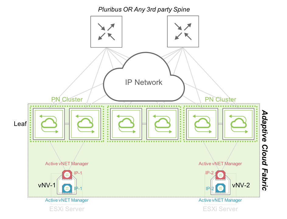
Figure 12 - vNET Manager Redundancy – Active/Active between Racks or Datacenters