Deploying Virtual Networks (vNETs) with Virtual Netvisor (vNV)
Deployment Workflow
You can create vNETs with vNV by using these high-level steps.
Step 1 |
Make sure all VMware prerequisites are met. For details, see the following sections: |
Step 2 |
Build your management and/or underlay network, depending on the topology you want to implement and create a fabric (management or inband). |
Step 3 |
Download the Pluribus Networks vNV OVA from your PN Cloud portal. |
Step 4 |
Deploy the vNV OVA image in your VMware vSphere environment and power on the VM. |
Step 5 |
Connect to the console or Linux shell (using SSH) on vNV-1 to run the switch-setup. If you’re not using a DHCP server, configure a static IP and default gateway as appropriate, along with DNS, NTP and time zone. Note: ensure you enable all host ports by default during the switch setup. |
Step 6 |
Ensure vNV-1 has IP connectivity to other nodes (either L2 or L3, depending on the design implemented). |
Step 7 |
Join vNV-1 with the fabric. |
Step 8 |
(Optional) - Create a range of VLANs to be used to map private VLANs to public VLANs. |
Step 9 |
Create a vNET with a vNET Manager and a vNET Admin user. |
Step 10 |
Associate Managed Ports to this vNET. |
Step 11 |
(Optional) - Associate Shared Ports to this vNET. |
In the event you want to provide full redundancy for the vNET Manager container, you instantiate a second vNV (vNV-2) by repeating Steps 3 to 6 and configure either VRRP between both vNVs or simply use 2 different IP addresses.
Prerequisites for deploying vNETs with vNV
Supported VMware® vSphere ESXi Hypervisor Versions
Pluribus Networks vNV is supported on the following VMware ESXi Hypervisor and vCenter Server versions:
- 6.0.x
- 6.5.x
ESXi Host Prerequisites for vNV
VMware ESXi hosts have the following prerequisites:
- You have installed and prepared vCenter Server for host management using the instructions from VMware.
- You have VMware vSphere Client installed or vCenter integration Plug-in in your browser.
- A specific license is not required for the vCenter Server to deploy vNV OVA images.
- You must configure at least two Port-groups:
- The Management Port-group (with Promiscuous mode, MAC address changes and Forged transmits parameters set to “Accept”) using one VLAN.
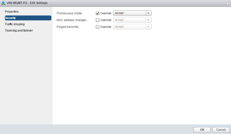
Figure 13 - Management Port-group Security Configuration on a Standard vSwitch
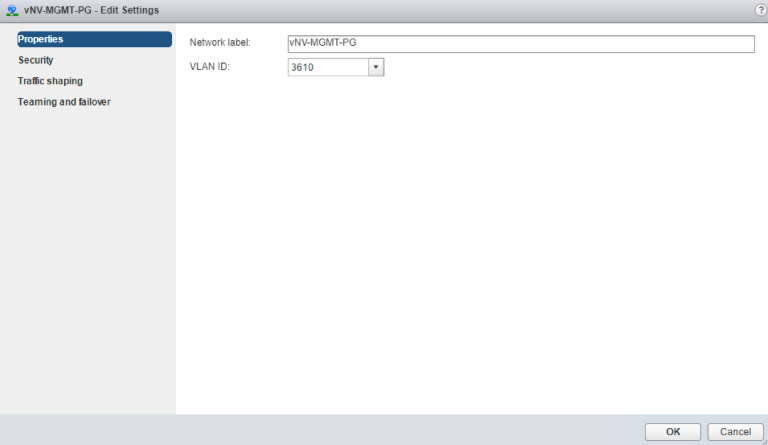
Figure 14 - Management Port-group VLAN Configuration on a Standard vSwitch
- In-band/Data Port-group (with Promiscuous mode, MAC address changes and Forged transmits parameters set to “Accept”) using a one VLAN or an 802.1q trunk, depending on the design.
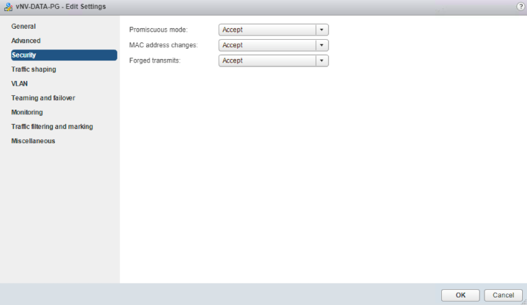
Figure 15 - Data/In-band Port-group Security Configuration on a Distributed vSwitch
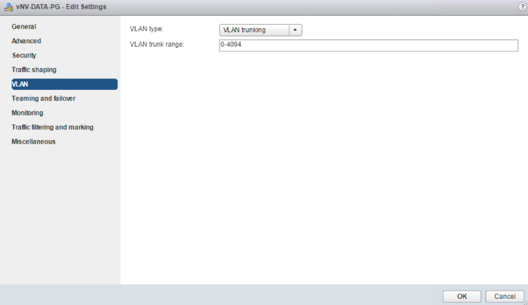
Figure 16 - Data/In-band Port-group VLAN Configuration on a Distributed vSwitch
- You have two physical NICs on each host for redundancy. Deployment is also possible with one physical NIC.
- If you are using a set of switches, make sure the inter-switches links carry all relevant VLANs, including the Management VLAN. The uplink should be a port, single trunk or VLAG, with all VLAN traffic configured on the host.
- Ensure the VMs to be used for vNV meet the minimum requirements listed in the following table:
Function |
Component |
Minimum Requirement |
vNV |
Hardware Version |
9 and higher |
Platform |
64-bit |
|
Type |
Other 64-bit Linux |
|
Processor |
4 vCPU (2 cores hyper threaded) |
|
Memory |
32 GB |
|
Disk |
40 GB in Thin Provisioning |
|
CPU Speed |
> 2 GHz |
Figure 17- Virtual Machine Minimum Requirements
Note: A first interface is created on vNV in addition to the two others used for Management and In-band. Do NOT use this interface, you must disconnect it during the deployment phase, it is not used by Netvisor.
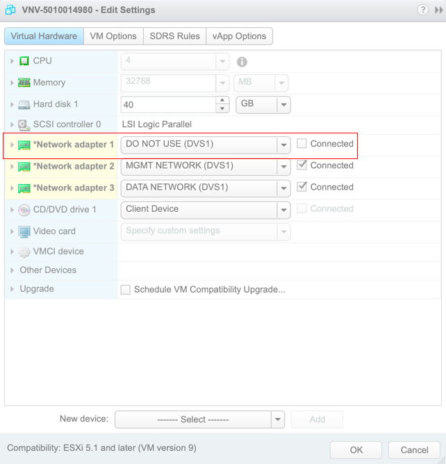
Figure 18 - vNV VM Configuration
Fabric Nodes Prerequisites
Fabric nodes have the following prerequisites:
- Fabric nodes must run the same Netvisor version to ensure a consistent and predictable behavior across the fabric.
- If you plan to deploy a management fabric with an L3 boundary to connect to vNVs, make sure to configure the default gateway on all switches.
- If you plan to deploy an in-band fabric with VRRP to provide a redundant default gateway to vNVs, ensure this VLAN is created and tagged on ports going to the ESXi servers where vNVs is deployed both on the cluster links and the subnet is redistributed (or advertised) in the IGP.
Deploying vNV
Before you begin this procedure, you must do the following:
- Know the location and image name of the OVA image required for the installation.
- You have already read the Prerequisites for deploying vNETs with vNV.
- For detailed information about using the Deploy OVF Template wizard, see the vSphere Virtual Machine Administration Guide.
- You have the following information available for creating a vNV VM and mapping the required port groups:
- A name for the new vNV that is unique within the inventory folder and up to 80 characters.
- The hostname and the inventory folder that contains the vNV you plan to use.
- The name and location of the VM datastore you plan to use.
- The names of the network port groups the VM you plan to use.
- The vNV IP address or an FQDN needed to access the VM.
Procedure:
Step 1 |
From the vSphere Web Client, find the host, cluster and/or resource pool where you want to deploy and right click > Deploy OVF Template… |
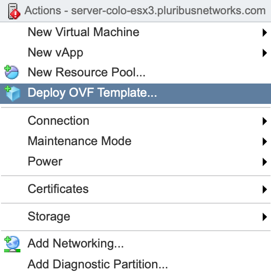
Figure 19 - Deploy OVF Template
Step 2 |
In the Template screen, specify the location of the OVA file and click Next. |
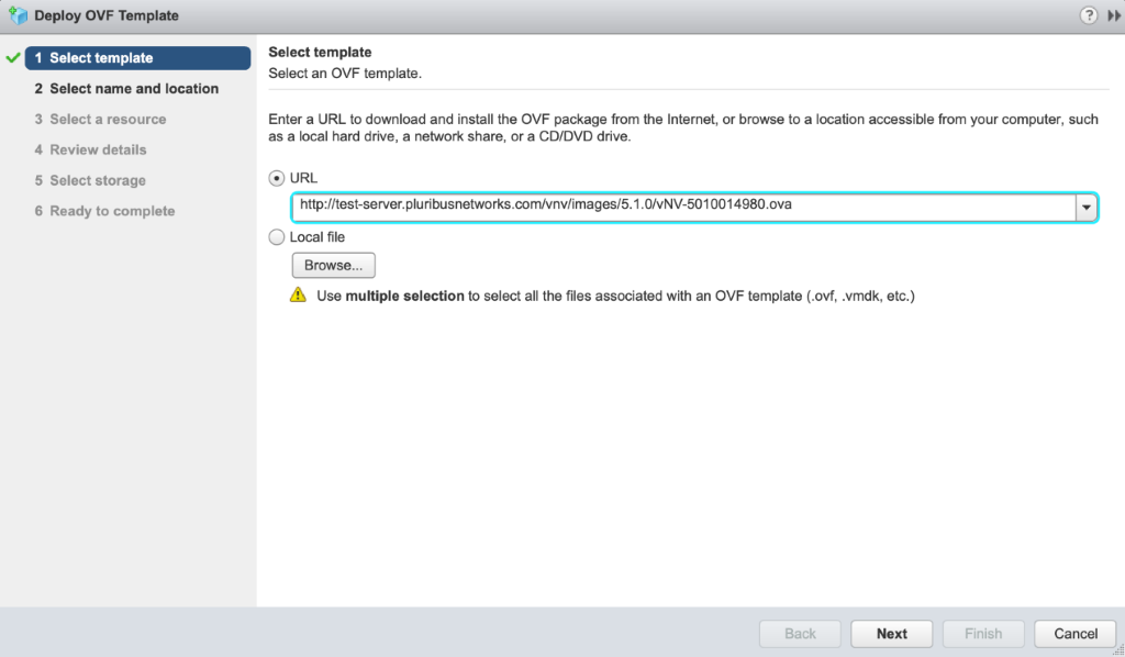
Figure 20 - Select OVF Template
Step 3 |
In the Name and Location screen, specify the Name of your vNV VM and select datacenter or folder in the Inventory and click Next. |
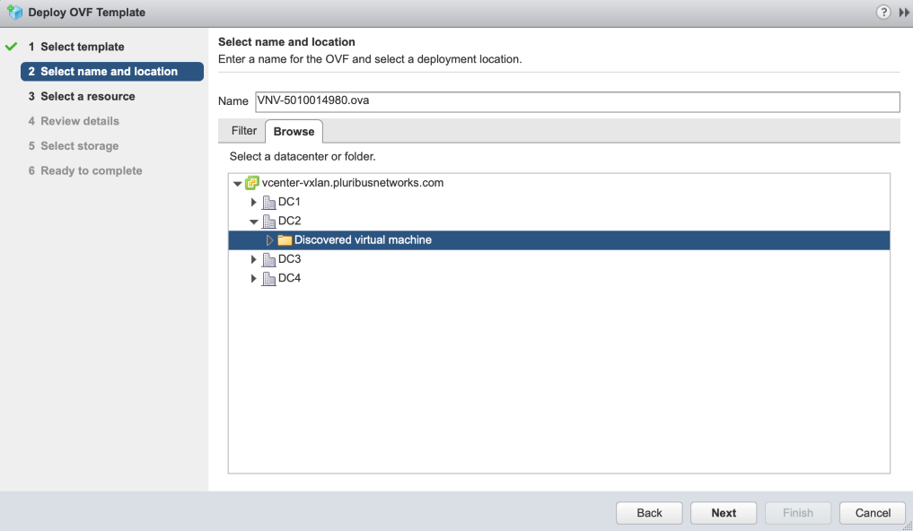
Figure 21 - Select Name and Location
Step 4 |
In the Resource screen, select host or cluster or resource pool and click Next. |
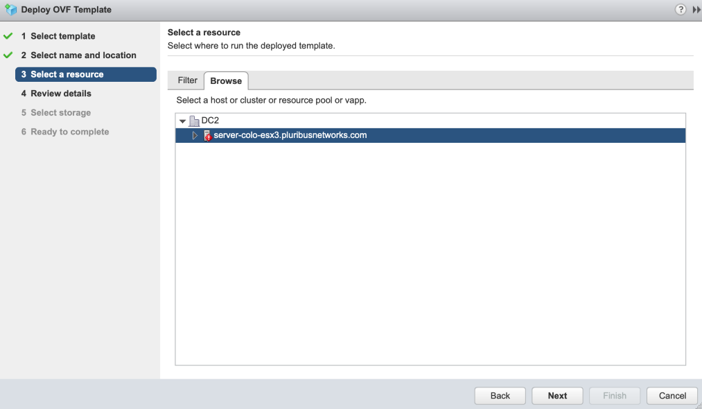
Figure 22 - Select Host or Cluster
Step 5 |
In the Review screen, verify details and click Next. |
Step 6 |
In the Select Storage screen, select Thin Provision from Select virtual disk format list, select the Datastore and click Next. |
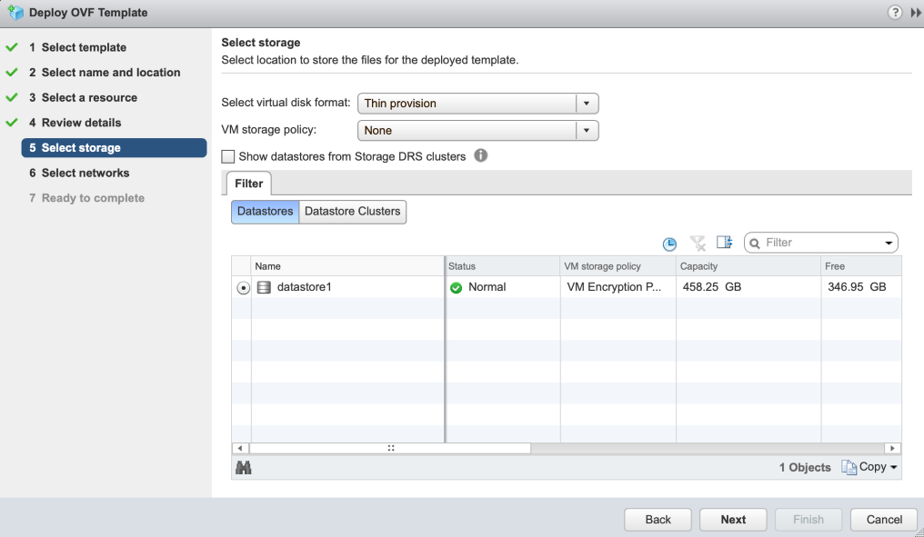
Figure 23 - Select Storage
Step 7 |
In the Networks screen, keep the default value of Destination Network. You modify network settings after deployment. Click Next. |
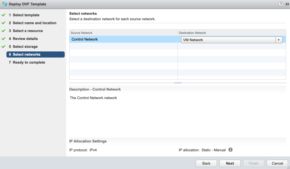
Figure 24 - Select Networks
Step 8 |
Verify if the configuration is correct in the Ready to Complete screen and click Finish. |
Note: If you are deploying vNV from vSphere Web Client, do not select 'Power on after deployment' option in the 'Ready to complete' screen.
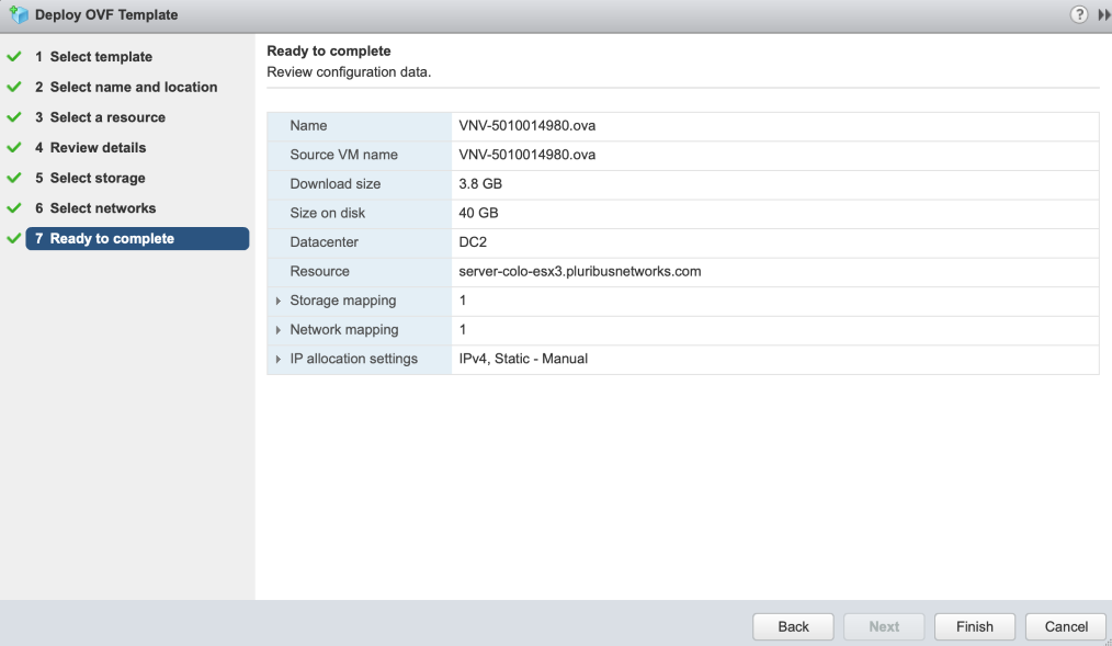
Figure 25 - Ready to Complete and Review Settings
You have completed the deployment of your vNV. Check the progress of vNV VM installation in the tasks section. Once the installation is completed and successful, go to next step. |
Step 9 |
Right click on vNV and select “Edit Settings” to modify network settings on your vNV. Disable “Network Adapter 1” (un-check Connect at Power On), select Management Network for “Network Adapter 2” and Inband/Data Network for “Network Adapter 3” and click OK." |
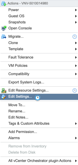
Figure 26 - Edit Settings
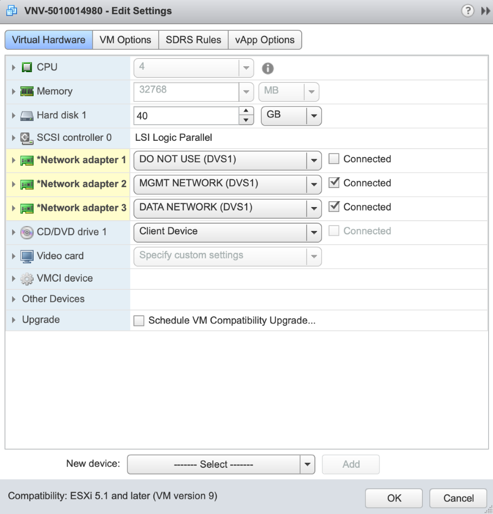
Figure 27 - Network Settings
Step 10 |
Power On your vNV VM. |
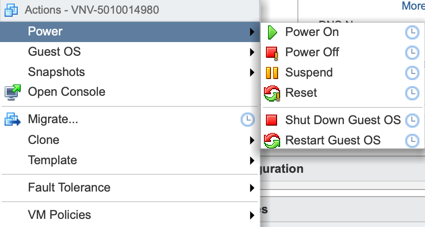
Figure 28 - Power on VM
After a period of time, the VM is booted and Netvisor is ready to run and form the fabric.
Step 11 |
Ensure fabric nodes are ready before joining the fabric with vNV using: |
CLI (network-admin@switch) > fabric-node-show |
An example of an output is shown below:
CLI (network-admin@sw11) > fabric-node-show format name,fab-name,mgmt-ip,in-band-ip,fab-tid,version,state,device-state name fab-name mgmt-ip in-band-ip fab-tid version state device-state ---- ---------- -------------- ------------ ------- --------------------------------- ---------------- ------------ sw11 Hybrid-ACF 10.36.10.11/24 10.0.11.1/30 6 5.1.0-5010014980,#50~14.04.1-Ubuntu online ok sw12 Hybrid-ACF 10.36.10.12/24 10.0.12.1/30 6 5.1.0-5010014980,#50~14.04.1-Ubuntu mgmt-only-online ok sw13 Hybrid-ACF 10.36.10.13/24 10.0.13.1/30 6 5.1.0-5010014980,#50~14.04.1-Ubuntu mgmt-only-online ok sw14 Hybrid-ACF 10.36.10.14/24 10.0.14.1/30 6 5.1.0-5010014980,#50~14.04.1-Ubuntu mgmt-only-online ok sw15 Hybrid-ACF 10.36.10.15/24 10.0.15.1/30 6 5.1.0-5010014980,#50~14.04.1-Ubuntu mgmt-only-online ok sw16 Hybrid-ACF 10.36.10.16/24 10.0.16.1/30 6 5.1.0-5010014980,#50~14.04.1-Ubuntu mgmt-only-online ok CLI (network-admin@sw11) > CLI (network-admin@sw11) > fabric-info name: Hybrid-ACF id: b000b27:5aa75367 vlan: 1 fabric-network: mgmt control-network: mgmt tid: 6 fabric-advertisement-network: in-band-mgmt CLI (network-admin@sw11) > |
This fabric is a six node fabric using management network.
Step 12 |
Login to your vNV VM:
Note: You can find the IP address of your vNV VM by simply looking at the IP Addresses of the VM in your VMware vSphere Web Client. See an example below: |
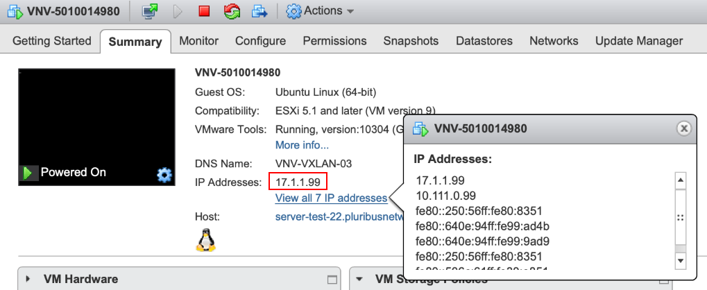
Figure 29 - Review IP Addresses
Note: The default credentials to connect to your vNV are: network-admin/admin
Step 13 |
Run the initial setup on vNV: |
johndoe-pc:~ johndoe$ ssh network-admin@10.36.10.169 The authenticity of host '10.36.10.169 (10.36.10.169)' can't be established. ECDSA key fingerprint is SHA256:5+RNHHFaWYJda15+0qJGB4VGMLmsqOo04h0GHeVTLGo. Are you sure you want to continue connecting (yes/no)? yes Warning: Permanently added '10.36.10.169' (ECDSA) to the list of known hosts. Last login: Fri Mar 16 22:32:34 2018 from thomas-pc.pluribusnetworks.com Netvisor OS Command Line Interface 5.1 By ANSWERING "YES" TO THIS PROMPT YOU ACKNOWLEDGE THAT YOU HAVE READ THE TERMS OF THE PLURIBUS NETWORKS END USER LICENSE AGREEMENT (EULA) AND AGREE TO THEM. [YES | NO | EULA]?: YES Switch setup required: Switch Name (vnv1): vnv1 network-admin Password: Re-enter Password: Mgmt IP/Netmask (dhcp): Mgmt IPv6/Netmask: In-band IP/Netmask (10.0.167.1/30): 10.0.169.1/30 In-band IPv6/Netmask: Gateway IP (10.36.10.254): Gateway IPv6: Primary DNS IP (10.34.30.1): Secondary DNS IP (10.34.30.2): Domain name (tme.pluribusnetworks.lab): Automatically Upload Diagnostics (yes): Enable host ports by default (yes): Switch Setup: Switch Name : vnv1 Switch Mgmt IP : 10.36.10.169/24 Switch Mgmt IPv6 : fe80::640e:94ff:fe68:a274/64 Switch In-band IP : 10.0.169.1/30 Switch In-band IPv6 : fe80::640e:94ff:fe68:92ee/64 Switch Gateway : 10.36.10.254 Switch IPv6 Gateway : :: Switch DNS Server : 10.34.30.1 Switch DNS2 Server : 10.34.30.2 Switch Domain Name : tme.pluribusnetworks.lab Switch NTP Server : Switch Timezone : Etc/UTC Switch Date : 2018-03-16,22:40:41 Upload Diagnostics : yes Enable host ports : yes Analytics Store : default Fabric required. Please use fabric-create/join/show Connected to Switch vnv1; nvOS Identifier:0x32be0968; Ver: 5.1.0-5010014980 CLI (network-admin@vnv1) > |
Step 14 |
Check for the existing fabrics: |
CLI (network-admin@vnv1) > fabric-show name id vlan fabric-network control-network tid fabric-advertisement-network ------------ ---------------- ---- -------------- --------------- --- ---------------------------- Hybrid-ACF b000b27:5aa75367 1 mgmt 6 in-band-mgmt fabric-show: Fabric required. Please use fabric-create/join/show CLI (network-admin@vnv1) > |
Step 15 |
Join the fabric: |
CLI (network-admin@vnv1) > fabric-join name Hybrid-ACF Joined fabric Hybrid-ACF. Restarting nvOS... Connected to Switch vnv1; nvOS Identifier:0x32be0968; Ver: 5.1.0-5010014980 CLI (network-admin@vnv1) > |
Step 16 |
Validate vNV-1 is now part of the management fabric: |
CLI (network-admin@vnv1) > fabric-node-show format name,fab-name,mgmt-ip,in-band-ip,fab-tid,version,state,device-state name fab-name mgmt-ip in-band-ip fab-tid version state device-state ---- ---------- --------------- ------------- ------- --------------------------------- ---------------- ------------ vnv1 Hybrid-ACF 10.36.10.169/24 10.0.169.1/30 7 5.1.0-5010014980,#50~14.04.1-Ubuntu online ok sw13 Hybrid-ACF 10.36.10.13/24 10.0.13.1/30 7 5.1.0-5010014980,#50~14.04.1-Ubuntu mgmt-only-online ok sw11 Hybrid-ACF 10.36.10.11/24 10.0.11.1/30 7 5.1.0-5010014980,#50~14.04.1-Ubuntu mgmt-only-online ok sw12 Hybrid-ACF 10.36.10.12/24 10.0.12.1/30 7 5.1.0-5010014980,#50~14.04.1-Ubuntu mgmt-only-online ok sw14 Hybrid-ACF 10.36.10.14/24 10.0.14.1/30 7 5.1.0-5010014980,#50~14.04.1-Ubuntu mgmt-only-online ok sw15 Hybrid-ACF 10.36.10.15/24 10.0.15.1/30 7 5.1.0-5010014980,#50~14.04.1-Ubuntu mgmt-only-online ok sw16 Hybrid-ACF 10.36.10.16/24 10.0.16.1/30 7 5.1.0-5010014980,#50~14.04.1-Ubuntu mgmt-only-online ok CLI (network-admin@vnv1) > |
Note: Repeat all these steps to deploy the second vNV to provide HA to the vNET Managers deployed on vNV.
Deploying vNETs
Step 1 |
Create a Public-to-Private VLAN Mapping. |
To allow independent VLAN IDs per tenant/vNET, the fabric administrator must configure a range of usable VLANs in the default 4k range of VLANs available (Public VLANs) to map to the private VLANs configured in each vNET:
CLI (network-admin@vnv1) > switch leaves vnet-public-vlans-modify vlans 1000-3999 |
In this example, the range 1000-3999 is used, which means every Private VLAN created is associated to a Public VLAN in that range.
The following table is an example of the mapping between Public and Private VLANs with the default vNET and two private vNETs created:
vNET |
Private VLAN ID |
Public VLAN ID |
global |
10 |
10 |
20 |
20 |
|
mgmt-vnet |
10 |
1000 |
20 |
1001 |
|
cust1-vnet |
10 |
1002 |
Figure 30 - Public and Private VLANs
The association between a range of Public VLANs are either reserved per vNET (static assignment) or shared across the different vNETs created.
Step 2 |
Create a Private vNET with a vNET Manager on vNV-1. |
To create a Private vNET, use the following command:
CLI (network-admin@vnv1) > switch vnv1 vnet-create name mgmt-vnet scope fabric vlan-type private num-private-vlans 100 vxlans 1010001-1014094 vnet-mgr-name mgmt-vnet-mgr1 |
Parameters:
- scope: defines the scope of this vNET. If this vNET must NOT be seen by other switches, don’t create it with a fabric scope, restrict this to a cluster scope or even local.
- vlan-type: defines the type of VLAN used in this vNET, consequently defines the type of vNET (private or public).
- num-private-vlans: defines the number of Private VLANs configured in this vNET. Here it is limited to 100 VLANs.
- vxlans: defines the range of VNIs used by the vNET administrator. In this example, the VNI convention is XXXYYYY:
- XXX is the tenant ID (101 for mgmt-vnet)
- YYYY is the VLAN ID (from VLAN 1 to VLAN 4094)
- vnet-mgr-name: defines the name of the vNET Manager created. For vNV-1, as a convention, we use mgmt- vnet-mgr1.
This creates a vNET with a vNET Manager container located on vNV-1.
Step 3 |
Configure vNET Administrator Credentials. |
CLI (network-admin@vnv1) > user-modify name mgmt-vnet-admin password password: |
Once the vNET Manager is created, to customize credentials for the vNET admin, use the following command:
Step 4 |
Create a vNET Manager on vNV-2. |
CLI (network-admin@vnv2) > switch vnv2 vnet-manager-create name mgmt-vnet-mgr2 vnet mgmt-vnet enable |
Once the vNET Manager is created, to customize credentials for the vNET admin, use the following command:
This creates a second vNET Manager container, located on vNV-2.
The output below shows two vNET Manager created on 2 different vNVs:
CLI (network-admin@vnv1) > vnet-manager-show name type scope vnet is-global vnet-service state -------------- -------- ------ --------- --------- ------------ ------- mgmt-vnet-mgr1 vnet-mgr fabric mgmt-vnet false shared enabled mgmt-vnet-mgr2 vnet-mgr fabric mgmt-vnet false shared enabled CLI (network-admin@vnv1) > |
Step 5 |
Configure the vNET Manager Interface on both vNVs. |
Option 5a |
On the Management vNIC. |
To provide an IP address to the vNET admin to manage his own vNET through the Management vNIC, use the following command:
CLI (network-admin@vnv1) > vnet-manager-interface-add vnet-manager-name mgmt-vnet-mgr1 ip 10.36.10.201/24 if mgmt vlan 0 vlan-type public |
Parameters:
- ip: IP address for the vNET Manager container.
- if: interface on the switch to be used to associate this IP with. This is either mgmt or data (front-facing ports). In this example, we’ll use the dedicated mgmt port.
- vlan: ID of the VLAN to be used on the port for this vNET Manager interface.
- vlan-type: type of VLAN to be used when a VLAN is used. If private is used, then the Private/Public VLAN mapping defines which VLAN is used in the Private vNET and the Public VLAN space (global vNET). As the mgmt port is used, no VLAN is used (“0”) and the VLAN type is public.
Note: It is important to either issue this command on vnv1 directly or specifying switch vnv1 if issued from another switch, otherwise this command outputs an error (as show below).
CLI (network-admin@sw11) > vnet-manager-interface-add vnet-manager-name mgmt-vnet-mgr1 ip 10.36.10.201/24 if mgmt vlan 0 vlan-type public vnet-manager-interface-add: vlan 0 not found CLI (network-admin@sw11) > |
We perform the same operation on the second vNV:
CLI (network-admin@vnv2) > vnet-manager-interface-add vnet-manager-name mgmt-vnet-mgr2 ip 10.36.10.202/24 if mgmt vlan 0 vlan-type public |
The output below shows the two vNET Manager interfaces configured on both vNVs:
CLI (network-admin@vnv1) > vnet-manager-interface-show format all layout vertical vnet-manager-name: mgmt-vnet-mgr1 nic: eth3 ip: 10.36.10.201/24 assignment: static assignment2: none assignment-linklocal: none mac: 66:0e:94:ec:38:92 vlan-type: public if: mgmt exclusive: no nic-config: enable nic-state: up mtu: 1500 sriov-vf: false mirror-traffic: false if-nat-realm: internal vnet-manager-name: mgmt-vnet-mgr2 nic: eth4 ip: 10.36.10.202/24 assignment: static assignment2: none assignment-linklocal: none mac: 66:0e:94:d8:a2:f5 vlan-type: public if: mgmt exclusive: no nic-config: enable nic-state: up mtu: 1500 sriov-vf: false mirror-traffic: false if-nat-realm: internal CLI (network-admin@vnv1) > |
Option 5b |
On the In-band vNIC. |
Alternatively, to provide an IP address to the vNET admin to manage his own vNET through the In-band vNIC, use the following command:
CLI (network-admin@vnv1) > vnet-manager-interface-add vnet-manager-name mgmt-vnet-mgr1 ip 10.10.10.1/24 if data vlan 100 vlan-type public |
Step 6 |
Configure a Default Gateway on vNET Managers. |
To provide connectivity to the vNET admin, a default gateway is configured in the vNET Manager container:
CLI (network-admin@vnv1) > vnet-manager-modify name mgmt-vnet-mgr1 gateway 10.36.10.254 |
Same operation on the second vNV:
CLI (network-admin@vnv2) > vnet-manager-modify name mgmt-vnet-mgr2 gateway 10.36.10.254 |
The output below shows the two vNET Managers with a gateway configured on both:
CLI (network-admin@vnv1) > vnet-manager-show name type scope vnet is-global vnet-service state gateway -------------- -------- ------ --------- --------- ------------ ------- ------------ mgmt-vnet-mgr1 vnet-mgr fabric mgmt-vnet false shared enabled 10.36.10.254 mgmt-vnet-mgr2 vnet-mgr fabric mgmt-vnet false shared enabled CLI (network-admin@vnv1) > |
CLI (network-admin@vnv2) > vnet-manager-show name type scope vnet is-global vnet-service state gateway -------------- -------- ------ --------- --------- ------------ ------- ------------ mgmt-vnet-mgr1 vnet-mgr fabric mgmt-vnet false shared enabled mgmt-vnet-mgr2 vnet-mgr fabric mgmt-vnet false shared enabled 10.36.10.254 CLI (network-admin@vnv2) > |
Note: In this example, the same network (physical and subnet) is used for both between the default vNET and the mgmt- vnet for the vNET Manager Interface. Another VLAN (part of the mgmt-vnet) could have defined on the Management vNIC of the vNV to have a complete isolation of the management subnets. An example for such scenario is shown below:
CLI (network-admin@vnv1) > vnet-manager-interface-add vnet-manager-name mgmt-vnet-mgr1 ip 10.36.10.102/24 if mgmt vlan 100 vnet mgmt-vnet vlan-type private |
An example is shown below for the in-band vNIC:
CLI (network-admin@vnv1) > vnet-manager-interface-add vnet-manager-name mgmt-vnet-mgr1 ip 10.10.10.1/24 if data vlan 200 vnet mgmt-vnet vlan-type private |
To configure an IP address on the second vNET Manager located on vNV-2, use the following command:
CLI (network-admin@vnv1) > vnet-manager-interface-add vnet-manager-name mgmt-vnet-mgr2 ip 10.36.10.103/24 if mgmt vlan 0 vlan-type public |
Step 7 |
Configure VRRP. |
To configure VRRP on a vNET Manager interface, use the following command:
CLI (network-admin@vnv1) > vnet-manager-interface-add vnet-manager-name mgmt-vnet-mgr1 ip 10.36.10.200/24 if mgmt vlan 0 vlan-type public vrrp-id 111 vrrp-primary eth3 vrrp-priority 250 |
We perform the same operation on the second vNV:
CLI (network-admin@vnv2) > vnet-manager-interface-add vnet-manager-name mgmt-vnet-mgr2 ip 10.36.10.200/24 if mgmt vlan 0 vlan-type public vrrp-id 111 vrrp-primary eth4 vrrp-priority 240 |
Note: This configuration only applies to the case where the 2 vNVs are in the same bridge/broadcast domain. The output below shows the two vNET Manager interfaces configured on both vNVs:
CLI (network-admin@vnv1) > vnet-manager-interface-show format all layout vertical vnet-manager-name: mgmt-vnet-mgr1 nic: eth3 ip: 10.36.10.201/24 assignment: static assignment2: none assignment-linklocal: none mac: 66:0e:94:ec:38:92 vlan-type: public if: mgmt exclusive: no nic-config: enable nic-state: up is-primary: true mtu: 1500 sriov-vf: false mirror-traffic: false if-nat-realm: internal vnet-manager-name: mgmt-vnet-mgr1 nic: eth8 ip: 10.36.10.200/24 assignment: static assignment2: none assignment-linklocal: none mac: 00:00:5e:00:01:6f vlan-type: public if: mgmt exclusive: no nic-config: enable nic-state: up is-vip: true vrrp-id: 111 vrrp-primary: eth3 vrrp-priority: 250 vrrp-adv-int(ms): 1000 vrrp-state: master mtu: 1500 sriov-vf: false mirror-traffic: false if-nat-realm: internal vnet-manager-name: mgmt-vnet-mgr2 nic: eth4 ip: 10.36.10.202/24 assignment: static assignment2: none assignment-linklocal: none mac: 66:0e:94:d8:a2:f5 vlan-type: public if: mgmt exclusive: no nic-config: enable nic-state: up is-primary: true mtu: 1500 sriov-vf: false mirror-traffic: false if-nat-realm: internal vnet-manager-name: mgmt-vnet-mgr2 nic: eth7 ip: 10.36.10.200/24 assignment: static assignment2: none assignment-linklocal: none mac: 00:00:5e:00:01:6f vlan-type: public if: mgmt exclusive: no nic-config: enable nic-state: down is-vip: true vrrp-id: 111 vrrp-primary: eth4 vrrp-priority: 240 vrrp-adv-int(ms): 1000 vrrp-state: slave mtu: 1500 sriov-vf: false mirror-traffic: false if-nat-realm: internal CLI (network-admin@vnv1) > |
With this configuration, the vNET Admin can login on his own slice of the fabric by using SSH on the IP address 10.36.10.200:
mgmt-pc:~ admin$ ssh mgmt-vnet-admin@10.36.10.200 mgmt-vnet-admin@10.36.10.200's password: Last login: Wed Jul 25 09:09:16 2018 from 10.10.10.10 Netvisor OS Command Line Interface 5.1 Connected to Switch vnv1; nvOS Identifier:0x680783ec; Ver: 5.1.0-5010014980 CLI (mgmt-vnet-admin@vnv1) > CLI (mgmt-vnet-admin@vnv1) > show vlan CLI (mgmt-vnet-admin@vnv1) > CLI (mgmt-vnet-admin@vnv1) > vnet-show switch name scope vlan-type vlans public-vlans num-private-vlans vxlans managed-ports shared-ports admin ------ --------- ------ --------- ----- ------------ ----------------- --------------- ------------- ------------ --------------- sw11 mgmt-vnet fabric private none none 100 1010001-1014094 none none mgmt-vnet-admin sw12 mgmt-vnet fabric private none none 100 1010001-1014094 none none mgmt-vnet-admin sw13 mgmt-vnet fabric private none none 100 1010001-1014094 none none mgmt-vnet-admin sw14 mgmt-vnet fabric private none none 100 1010001-1014094 none none mgmt-vnet-admin sw15 mgmt-vnet fabric private none none 100 1010001-1014094 none none mgmt-vnet-admin sw16 mgmt-vnet fabric private none none 100 1010001-1014094 none none mgmt-vnet-admin sw18 mgmt-vnet fabric private none none 100 1010001-1014094 none none mgmt-vnet-admin vnv1 mgmt-vnet fabric private none none 100 1010001-1014094 none none mgmt-vnet-admin vnv2 mgmt-vnet fabric private none none 100 1010001-1014094 none none mgmt-vnet-admin CLI (mgmt-vnet-admin@vnv1) > |
In this output, we can see when we SSH to the VIP, we end up connected to the master VRRP, in this example, vnv1.