Configuring Multiple VXLAN Next Hops on a Single Egress Port
Prior to the Netvsior ONE 6.1.0 release, a hardware limitation on the Broadcom ASICs allowed Netvisor ONE to configure only one egress port to next hop index (NHI) mapping per physical egress port or trunk port. This limitation obstructed the creation of multiple VXLAN tunnels in the hardware if the respective next hops resolved on the same physical port or trunk port.
From Netvisor ONE version 6.1.0 onward, you can create multiple VXLAN tunnel next hops on the same egress trunk port or physical egress port due to a resolution in the hardware restriction.
This feature is available on the following Trident3, Trident2+, and Maverick platforms of Pluribus switches:
|
|
|
|
|
|
|
|
|
|
|
|
|
|
|
|
|
|
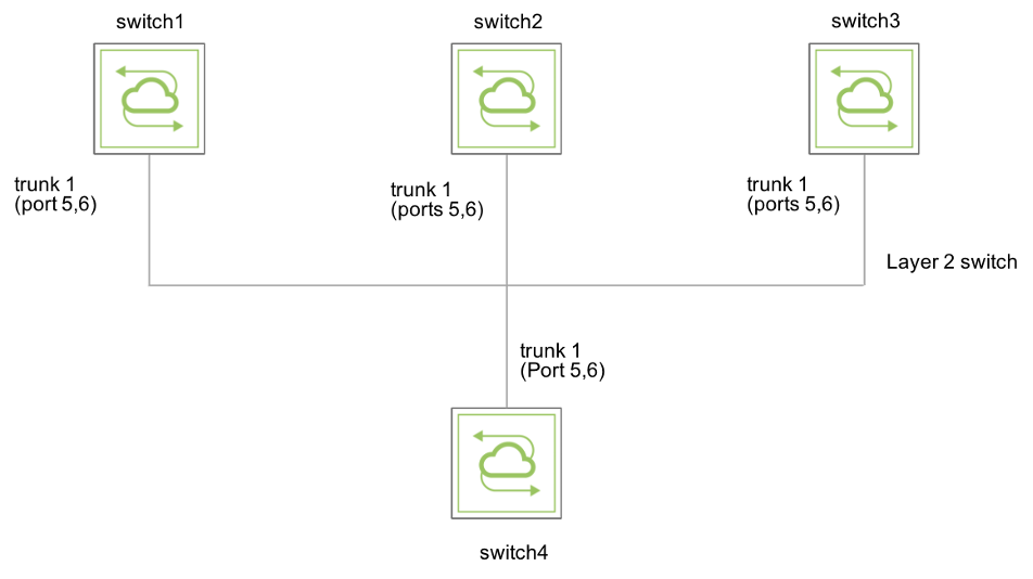
For example, consider a basic sample topology (Figure 8-18) consisting of four switches interconnected through physical and trunk ports. Each switch is connected to other three switches using a trunk port or a physical port (trunk port 1/ports 5, 6 in the diagram). They are also inter-connected via a layer 2 network. To build a VXLAN-based fabric, you can configure a full mesh of VXLAN tunnels connecting all the switches to one another.
Prior to Netvisor ONE version 6.1.0, the switches were unable to establish three separate VXLAN tunnels to other three switches because their next hops were all routed through the same trunk port. In other words, you could achieve only a one-to-one mapping of egress ports to VXLAN next hops.

Figure 8-18 - Topology with Physical Egress Ports or Trunk Ports
With Netvisor ONE 6.1.0, you can configure a one-to-many mapping of:
- Physical egress ports to VXLAN next hops, or
- Trunk egress ports to VXLAN next hops
To configure multiple VXLAN tunnels, use the command:
CLI (network-admin@switch4) > tunnel-create
|
tunnel-create |
This command creates a tunnel between two switches. |
|
scope local|cluster |
Specify the scope. |
|
name <name-string> |
Enter the name of the tunnel you want to configure. |
|
Specify any of the following options: |
|
|
vrouter-name <vrouter name> |
Specify the name of the vRouter service |
|
local-ip <ip-address> |
Specify the local IP address. |
|
remote-ip <ip-address> |
Specify the remote host IP address. |
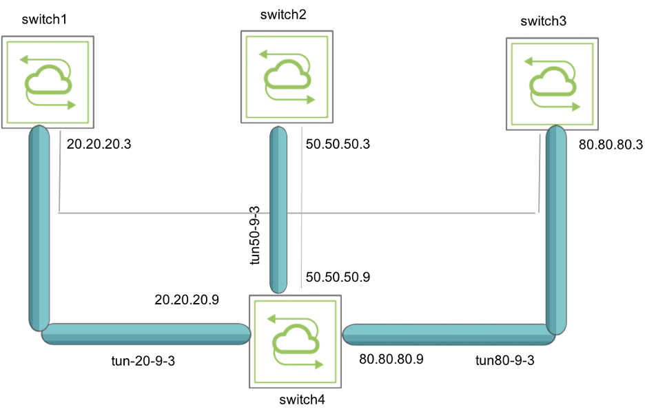
As an example, in the above topology (Figure 8-18), configure three static VXLAN tunnels to connect switch4 to switch1, switch2, and switch3 by using the commands:
CLI (network-admin@switch4*) > tunnel-create scope local name tun20-9-3 vrouter-name vr-tucana local-ip 20.20.20.9 remote-ip 20.20.20.3
CLI (network-admin@switch4*) > tunnel-create scope local name tun50-9-3 vrouter-name vr-tucana local-ip 50.50.50.9 remote-ip 50.50.50.3
CLI (network-admin@switch4*) > tunnel-create scope local name tun80-9-3 vrouter-name vr-tucana local-ip 80.80.80.9 remote-ip 80.80.80.3
View the configuration details using the command:
CLI (network-admin@switch4*) > tunnel-show

The output above shows that the VXLAN tunnels are created and are functional as in Figure 8-19.

Figure 8-19 - Topology with VXLAN tunnels
To view the details of each tunnel, use the following commands:
CLI (network-admin@switch*) > vlan-show id 20
id type auto-vxlan replicators scope description active stats ports untagged-ports active-edge-ports
-- ------ ---------- ----------- ----- ----------- ------ ----- ---------- -------------- -----------------
20 public no none local vlan-20 yes yes 0-1,125,272 none 0,272
CLI (network-admin@switch4*) > vlan-show id 50
id type auto-vxlan replicators scope description active stats ports untagged-ports active-edge-ports
-- ------ ---------- ----------- ----- ----------- ------ ----- ----------- -------------- ----------------
50 public no none local vlan-50 yes yes 0-1,125,272 none 0,272
CLI (network-admin@switch*) > vlan-show id 80
id type auto-vxlan replicators scope description active stats ports untagged-ports active-edge-ports
-- ------ ---------- ----------- ----- ----------- ------ ----- ----------- -------------- ----------------
80 public no none local vlan-80 yes yes 0-1,125,272 none 0,272
