
Configuring Cluster over Layer 3
Clustering switch pairs over Layer 3 requires the creation of VXLAN tunnels between the cluster nodes through the intermediate (spine) switch(es). The VXLAN tunnels function as virtual cluster links and carry both control traffic (if control is over in-band) and data traffic.
Please refer to the Configuring VXLAN chapter for more information on the VXLAN technology and configuration.
Note: A cluster over Layer 3 configuration takes longer to achieve traffic convergence in comparison to a traditional cluster using direct cluster links. This is because in the former case cluster communication is made possible by VXLAN tunnels, which come up only after Layer 3 convergence.
Note: Currently cluster over Layer 3 uses automatic tunnels called auto-tunnel-cluster (as shown in the figure below). It is not compatible with manual VXLAN tunnels.
Note: Starting from release 7.0.0/7.0.1, NetVisor OS supports the cluster over Layer 3 feature on the following platforms:
- On NetVisor 7.0.0: Freedom (Edgecore)- F9480-V (AS7326-56X), F9460-X (AS5835-54X), F9460-T (AS5835-54T)
- On NetVisor 7.0.0: Dell S5200 Series, NRU03, and NRU-S0301.
- On NetVisor 7.0.1: Dell S4100 Series
Consider for example, the topology below where the cluster over Layer 3 feature is configured. In this figure, two cluster pairs are connected via Layer 3 over a spine node.
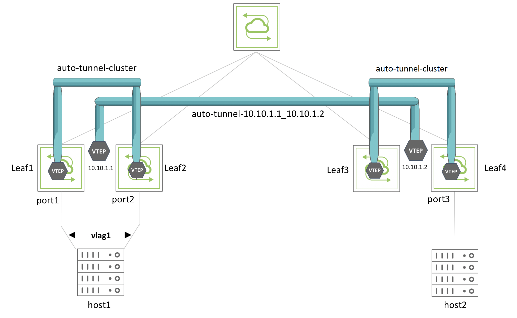
Figure 7-8 – Cluster over L3 Topology with vLAG
The VXLAN tunnel called auto-tunnel-cluster in Figure 7-8 is a special local tunnel between the leaf switch pairs created over the interconnections with the spine switch. The tunnel called auto-tunnel-10.10.1.1_10.10.1.2 is the regular VXLAN connection between VTEP VIPs 10.10.1.1 and 10.10.1.2. The vLAG named vlag1 is formed using port1 of Leaf1 and port2 of Leaf2.
To configure cluster over Layer 3, use the cluster-create command:
CLI (network-admin@Leaf1) > cluster-create
|
cluster-name |
Specify the name of the cluster. |
|
cluster-node-1 fabric-node name |
Specify the name of the first switch in the cluster |
|
cluster-node-2 fabric-node name |
Specify the name of the second switch in the cluster |
|
vxlan 0..16777215 |
Specify the VXLAN ID for cluster over L3. |
|
node1-ip ip-address |
Specify the IP address of cluster node 1. |
|
node2-ip ip-address |
Specify the IP address of cluster node 2. |
|
validate|no-validate |
Validate the inter-switch links and state of the switches in the cluster. |
|
cluster-sync-timeout milliseconds |
Specify the amount of time before a cluster times out during synchronization. The allowed range is between 500ms and 2000ms. |
|
cluster-sync-offline-count number |
Specify the number of missed synchronizations before the cluster goes offline. |
Note: The VXLAN ID should be a non-null value to enable cluster over L3.
For example, to configure the cluster that includes Leaf1 and Leaf2, use the command:
CLI (network-admin@Leaf1) > cluster-create name cluster1 cluster-node-1 Leaf1 cluster-node-2 Leaf2 vxlan 40940 node1-ip 192.168.1.1 node2-ip 192.168.1.2
This command creates the bidirectional tunnel auto-tunnel-cluster between Leaf1 and Leaf2 with a local scope and adds the cluster VXLAN ID to the tunnel.
To view the cluster configuration, use the command:
CLI (network-admin@Leaf1) > cluster-show format state,cluster-node-1,cluster-node-2,vxlan,tunnel-name,node1-ip,node2-ip,mode,ports,remote-ports
state cluster-node-1 cluster-node-2 vxlan tunnel-name local-ip remote-ip mode ports remote-ports
------ --------------- --------------- ----- ------------------- ----------- ----------- ------ ------- ------------
online Leaf1 Leaf2 40940 auto-tunnel-cluster 192.168.1.1 192.168.1.2 slave none none
online Leaf1 Leaf2 40940 auto-tunnel-cluster 192.168.1.1 192.168.1.2 master none none
online Leaf3 Leaf4 0 :: :: master 1-3,272 1-3,272
online Leaf3 Leaf4 0 :: :: slave 1-3,272 1-3,272
To view the tunnel configuration, use the command:
CLI (network-admin@Leaf1) > tunnel-show format name,scope,local-ip,remote-ip,state
name scope local-ip remote-ip state
------------------------------- ------- ----------- ----------- -----
auto-tunnel-cluster local 192.168.1.1 192.168.1.2 ok
auto-tunnel-10.10.1.1_10.10.1.2 cluster 10.10.1.1 10.10.1.2 ok
The auto-created tunnel auto-tunnel-10.10.1.1_10.10.1.2 between endpoints 10.10.1.1 and 10.10.1.2 links the cluster of Leaf1 and Leaf2 to the cluster of Leaf3 and Leaf4.
To display the tunnels and the associated VXLAN IDs, use the command:
CLI (network-admin@Leaf1) > tunnel-vxlan-show
name vxlan
----------------------------------- -----
auto-tunnel-cluster 40940
auto-tunnel-cluster 1000
auto-tunnel-cluster 1001
auto-tunnel-cluster 1002
auto-tunnel-10.10.1.1_10.10.1.2 1000
Use the vlag-show command to display the vLAG configuration:
CLI (network-admin@Leaf1*) > vlag-show format name,switch,port,peer-switch,peer-port,status,local-state,peer-state,
name switch port peer-switch peer-port status local-state peer-state
----- ------ ---- ----------- --------- ------ ----------- ----------
vlag1 Leaf1 1 Leaf2 2 normal enabled,up enabled,up
You can modify a traditional cluster with direct links to a cluster over Layer 3 with VXLAN tunnels by using the cluster-modify command. You must disable the direct links before making this change in configuration:
CLI (network-admin@Leaf1) > cluster-modify name cluster10 vxlan 8188 node1-ip 10.10.11.1 node2-ip 10.10.11.2
Note: Arista Networks requires that the direct links be disabled and recommends rebooting both the cluster switches after you modify a traditional cluster with direct links to a cluster over Layer 3.
To perform the reverse transition from cluster over Layer 3 to traditional cluster, you must enable the direct cluster link(s) and specify vxlan as 0 in the cluster-modify command, like so:
CLI (network-admin@Leaf1) > cluster-modify name cluster10 vxlan 0
Note: Arista Networks recommends rebooting both the cluster switches after you modify a cluster over Layer 3 to a traditional cluster with direct links.
Note: When configuring BGP on the network to support the cluster over L3 functionality, you can use either of the two following options: (a) use eBGP with allow-as-in-origin or (b) use iBGP with the recommended practices as below:
a. You allocate a dedicated port (not a cluster port or a loopback port, which are not suitable) and assign a VLAN with a vRouter interface to it so that the iBGP interface stays up. Also, ensure that the VNI associated to the VLAN is added to the cluster’s VTEP.
b. Use a route map, as shown below, on both cluster nodes, configured for in-band communication to stay up:
CLI (network-admin@Leaf1) > vrouter-prefix-list-add vrouter-name <vrouter-name> name <list-name> seq <number> action permit prefix <peer ip/mask>
CLI (network-admin@Leaf1) > vrouter-route-map-add vrouter-name <vrouter-name> name <map-name> seq <number> action permit match-prefix <list-name>
CLI (network-admin@Leaf1) > vrouter-bgp-add vrouter-name <vrouter-name> neighbor <bgp-neighbor-ip> remote-as <as-number> next-hop-self bfd multiprotocol ipv4-unicast,ipv6-unicast weight 0 neighbor-keepalive-interval 10 neighbor-holdtime 30 route-map-out <map-name>
Starting from release 7.0.0 NetVisor OS also supports the configuration of VXLAN-based bridge domains (BDs) on clusters over Layer 3. (Refer to the Configuring Advanced Layer 2 Transport Services chapter for more details on bridge domains.)
With this enhancement it is not required to allocate reserved VLANs for clusters over Layer 3. However, a reserved VLAN is still needed if the BD needs to traverse a traditional cluster. (Within a fabric it’s possible to have a mix of traditional clusters and clusters over Layer 3.)
It is also possible to modify a traditional cluster to become a cluster over Layer 3, and vice versa, when BDs are configured on it. Cluster links must be disabled before configuring a cluster over Layer 3.
On the other hand, the transition from cluster over Layer 3 to a traditional cluster requires a reserved VLAN to have been provisioned and the cluster links to be operational.
To configure a cluster over Layer 3 you can use the cluster-create command as shown above:
CLI (network-admin@Leaf1) > cluster-create name cluster1 cluster-node-1 Leaf1 cluster-node-2 Leaf2 vxlan 40940 node1-ip 192.168.1.1 node2-ip 192.168.1.2
Then a BD can be configured like so:
CLI (network-admin@Leaf1) > bridge-domain-create name bd-cluster-o-l3 scope fabric vxlan 800800 [rsvd-vlan 4080]
where the reserved VLAN is no longer needed if the BD doesn’t need to traverse a traditional cluster.
Then the BD can be configured on the desired set of ports, for example like so:
CLI (network-admin@Leaf1*) > bridge-domain-port-add name bd-cluster-o-l3 port 1 outer-vlan 1000 inner-vlan 800
CLI (network-admin@Leaf1*) > l2-table-show bd bd-cluster-o-l3 format mac,bd,vlan,inner-vlan,vxlan,ip,ports,state,status,
mac bd vlan inner-vlan vxlan ip ports state status
----------------- --------------- ---- ---------- ------ ------------ ----- ------ ------
00:20:fc:81:4d:08 bd-cluster-o-l3 800 800800 205.95.95.62 tunnel host
00:12:c0:80:33:1e bd-cluster-o-l3 1000 800 800800 205.95.95.51 1 active host
CLI (network-admin@Leaf1*) > bridge-domain-show
name scope ports vxlan-inner-packet mac-learning l2-tunneling
--------------- ------ ----- ------------------ ------------ ------------
bd-cluster-o-l3 fabric 1 auto on none