
L3 OVL - Distributed VRF
Layer 3 Configuration - Distributed VRF (Virtual Routing and Forwarding)
Virtual Routing and Forwarding (VRF) is a technology used in network routers to allow more than one routing table to exist in a router and work concurrently. VRF increases functionality by allowing segmented network paths without using multiple devices.
Netvisor ONE Unified Cloud Fabric adds Layer 3 segmentation to VXLAN interconnections with the support of VRF (Virtual Routing and Forwarding) instances, complementing the vRouter construct and offering a highly scalable distributed routing solution to network architects.
Netvisor supports VRF as a hardware technology allowing multiple routing spaces to coexist on the same distributed fabric architecture. Furthermore, with the addition of the Anycast Gateway functionality, the Unified Cloud Fabric enables distributed forwarding at the first-hop router and intrinsic VM mobility capabilities across complex multi-site data center designs. This approach guarantees the maximum VRF scalability possible, limited only by the specific forwarding ASIC capabilities.
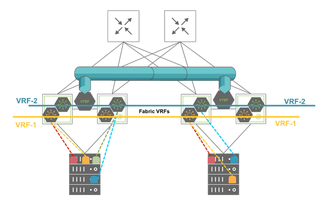
East-West Traffic Segmentation with Multiple VRF Instances
Netvisor Fabric VRFs have the following advantages:
•High scalability with support for many VRF instances on a single fabric node (in the order of thousands depending on hardware capacity, especially with newer ASICs and as an aggregate number fabric-wide).
•High performance distributed routing of East-West traffic at the Top-of-Rack (ToR) switch level. The distributed routing capability hosted on each leaf node avoids the need for hair pinning traffic to a centralized vRouter.
•Small forwarding state footprint to manage on each node.
•Use native redundancy without the need for dedicated redundancy protocols and potentially extra overhead.
•Dual-stack supported for both IPv4 and IPv6 subnets.
•Simple fabric-wide configuration and management (typical provisioning overhead is proportional to: (number_of_VRFs + number_of_VLANs + number_of_switches) instead of the industry average of up to (number_of_VLANs * number_of_switches).
•Automatically stretch IPv4 and IPv6 subnets to multiple locations without extra configuration.
•Import / Export subnet prefixes between VRFs using an innovative feature called virtual service group (vSG).
There are features and functions used in UNUM Manager and UNUM Analytics that are common throughout the user interface (UI). Please refer to the Common Functions section for more information on the use of these functions and features.
Manage VRF
Selecting Manager → Layer 3 → Distributed VRF displays theDistributed VRF dashboard with a list of any existing VRF settings.
Select the applicable Fabric from the left-hand navigation bar and the dashboard updates showing all VRF entries from all switches within the Fabric.
Note: If no entries exist a "No Data Exists" message is displayed. You must first configure an entry on a switch. Prerequisite settings and configuration may be required.
The dashboard displays a list of existing VRF entries by Switch. Additional parameters include: Name,vNET Id, Scope, Anycast MAC, VRF GW, VRF GW2, VRF GW IP6, VRF GW2 IP6, Active, Router Mac, HW VRID, Enable, and L3 VNI. The VRF information is scope dependent meaning either Fabric, Local or Cluster.
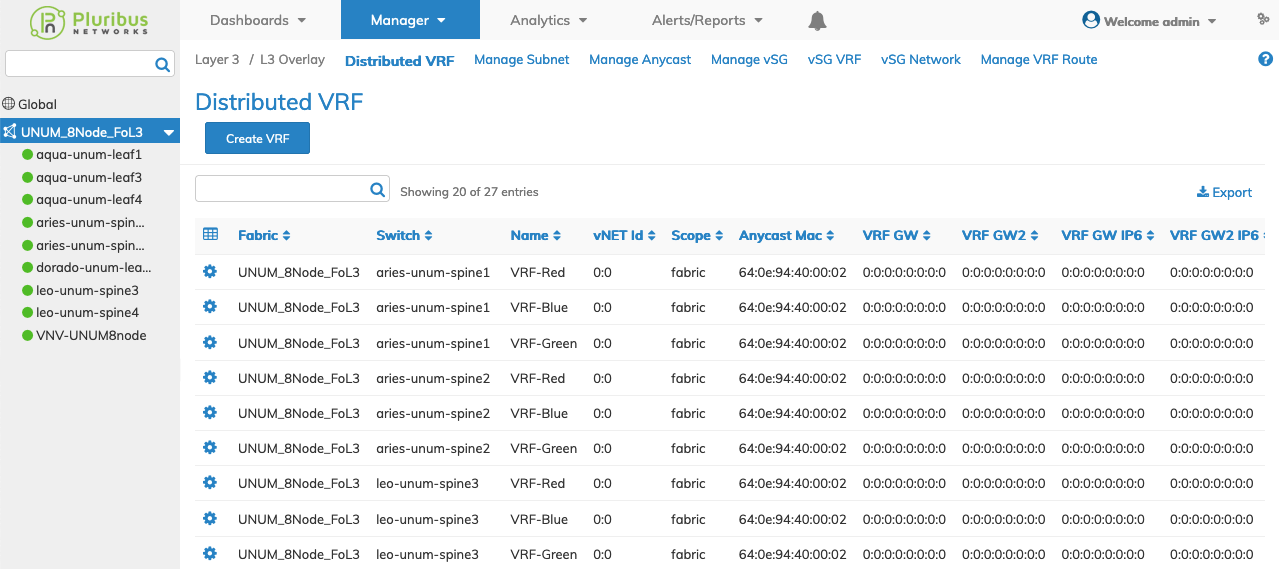
Distributed VRF Fabric Dashboard
Select the applicable switch from the fabric and the dashboard updates automatically with VRF settings.
The dashboard displays a list of existing VRF entries by Name. Additional parameters include: vNET Id, Scope, Anycast MAC, VRF GW, VRF GW2, VRF GW IP6, VRF GW2 IP6, Active, Router Mac, HW VRID, Enable, and L3 VNI. The VRF information is scope dependent meaning either Fabric, Local or Cluster.

Distributed VRF Switch Dashboard
Create a VRF
To add a VRF to a switch click Create VRF and enter the configuration parameters which include:
•Switch / FRG – Select switch or a FRG (Fabric Resource Group) from the drop down list.
•Name – (required) The name assigned to the VRF.
Select additional field parameters by clicking on the ![]() icon. Additional fields include:
icon. Additional fields include:
•Scope – Scope of the VRF, either Fabric, Local or Cluster.
•Enable – (checkbox) Enable or disable VRF routing.
•vNET Id – vNET for the VRF.
•Description – A description for the VRF.
•VRF Gw – gateway IP address.
•VRF Gw2 – gateway IP address 2.
•VRF Gw Ip6 – IPv6 gateway address.
•VRF Gw2 Ip6 – IPv6 gateway address 2.
•L3 VNI – L3 VNID.
•Anycast Mac For Forwarding – (checkbox) Enable or disable Anycast Mac for forwarding.
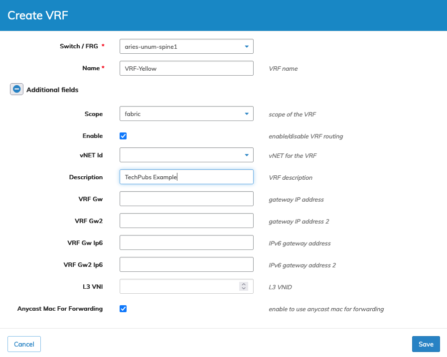
Distributed VRF Switch Create
Click Save to continue or Cancel to return to the previous screen without saving any changes.
The new VRF is added to the Dashboard.
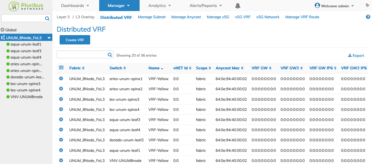
Distributed VRF Create - Added to Dashboard
Modify a VRF
To modify a VRF entry use Edit by selecting the Cog ![]() icon to make changes to the VRF configuration.
icon to make changes to the VRF configuration.
Click the ![]() icon for Additional Fields which include:
icon for Additional Fields which include:
•Enable – (checkbox) enable or disable VRF routing.
•Description – VRF Description.
•VRF Gw – gateway IP address.
•VRF Gw2 – gateway IP address 2.
•VRF Gw Ip6 – IPv6 gateway address.
•VRF Gw2 Ip6 – IPv6 gateway address 2.
•L3 VNI – L3 VNID.
•Anycast Mac For Forwarding – (checkbox) Enable or disable Anycast Mac for forwarding.
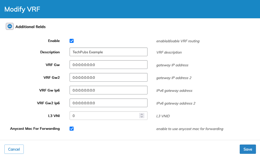
Distributed VRF Modify
Click Save to continue or Cancel to return to the previous screen without saving any changes.
Delete a VRF
To delete a VRF entry use Delete by selecting the Cog ![]() icon.
icon.
A confirmation message requires an acknowledgment to continue deletion.

Distributed VRF Delete VRF Confirm
Click OK to continue or Cancel to return to the previous screen without making any changes.
Distributed VRF Example
In the following example, UNUM created three VRFs named TENANT-GREY, SERVICE-AMBER, and TENANT-GREEN as a prerequisite for configuring vSG.
The Active column indicates a SUBNET exists for SERVICE-AMBER, marked as "true," while the other VRFs do not yet have a SUBNET.

Distributed VRF Example
To configure a SUBNET for other VRFs proceed to Manage Subnet.
