
Cluster - Manage VLAG
Layer 2 Configuration – VLAGS
There are features and functions used in Arista NetVisor UNUM and Insight Analytics that are common throughout the user interface (UI). Please refer to the Common Functions section for more information on the use of these functions and features.
Host Facing VLAGs
NetVisor UNUM version 6.3.0 supports creating host-facingVLAGs in the L2/L3 Fabric Playbooks using CSV files and the NetVisor UNUM interface.
The virtual chassis logical model can be effectively used to enable an advanced capability called multi-chassis link bundling/port channeling. This feature is also known as MC-LAG (Multi-Chassis Link Aggregation Group). An MC-LAG is a cross-device link bundle (i.e., Trunk). It typically has at least one port member on one switch and another port member on a backup switch. It can be facing downstream toward an endpoint (configured with a regular LAG on its end) or upstream toward another switch or router (also using a regular LAG or even an MC-LAG).
Arista Networks' implementation of MCLAG is called VLAG (Virtual Link Aggregation Group) on a switch cluster. That, in practice, means in order to be able to configure a VLAG, first set up a cluster pair.
The cluster trunk is just a regular LAG but is the pivot around which various important functions revolve. First off, it provides a critical communication channel utilized for cluster synchronization activities and protocol exchanges. It is also instrumental for supporting the MC-LAG (a.k.a. VLAG) function on the cluster, as it can function as a backup forwarding path during failover scenarios. From a high-level perspective, a VLAG is a single logical but physically redundant upstream or downstream connection across a pair of cluster switches. In other words, physically, it’s a triangular topology that includes the cluster trunk, while logically, it appears just as if it were a point-to-point multi-link connection.
For instance, using clusters with VLAGs is a technique often chosen to avoid using the Spanning Tree Protocol (STP) for Layer 2 redundancy.
This property makes active-active VLAGs ideal for many Layer 2 or Layer 3 network designs.

VLAG Cluster Example
Furthermore, using the same approach allows for the interconnecting of dual-homed servers to leaf switches.

VLAG Example - Multi-Chassis
The following example illustrates a common use case of the interconnection of leaf and spline clusters to provide high availability using the virtual chassis/four-way VLAG technique.
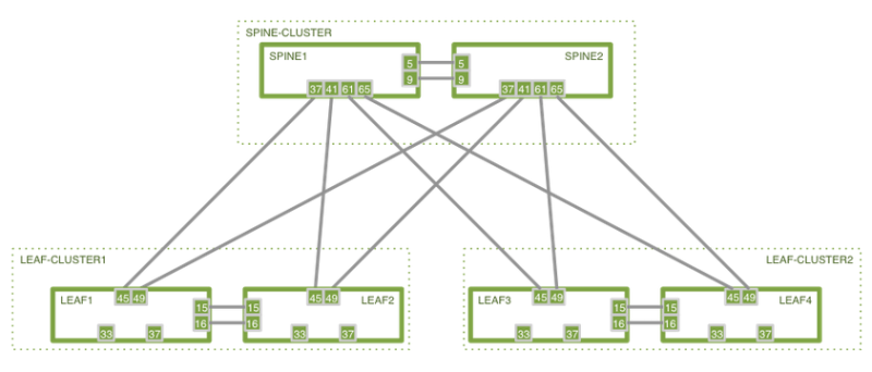
High Availability Cluster-based Spine/Leaf Design
Manage VLAG
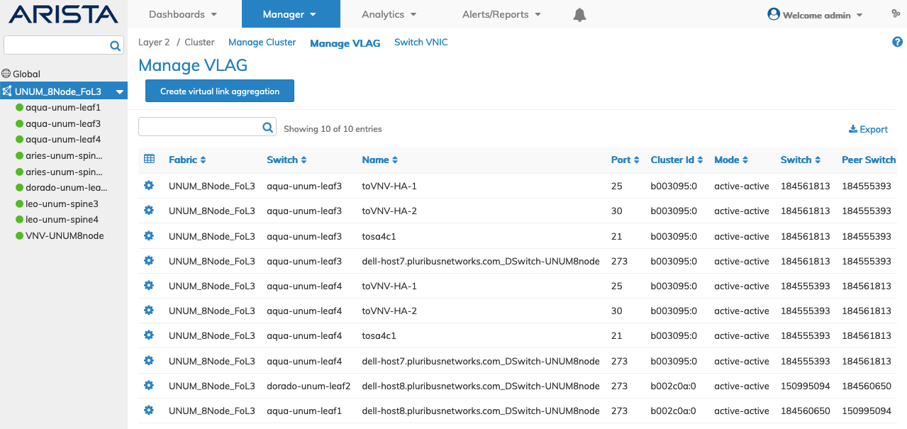
Selecting Manage → Layer 2 → Manage VLAG displays the Manage VLAG dashboard with a list of any existing VLAG entries.
Select the applicable Fabric from the left-hand navigation bar and the dashboard updates showing all VLAGs from all switches within the Fabric.
Note: If no entries exist a "No Data Exists" message is displayed. You must first configure an entry on a switch. Prerequisite settings and configuration may be required.
The dashboard displays a list of existing VLAG entries by Fabric. Additional parameters include: Switch, Name, Port, Cluster Id, Mode, Switch, Peer Switch, Peer Port, Status, Local State, and LACP Mode.
Manage VLAGS Fabric Dashboard
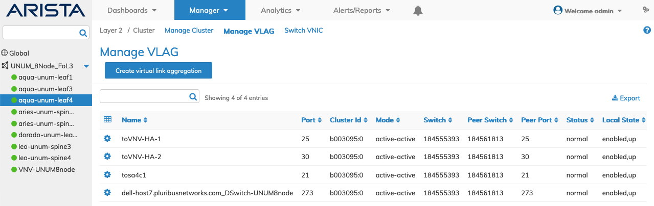
Select the applicable switch from the fabric and the dashboard updates automatically with VLAG settings.
The dashboard displays a list of existing VLAG entries. Parameters include: Name, Port, Cluster Id, Mode, Switch, Peer Switch, Peer Port, Status, Local State, and LACP Mode.
Manage VLAGS Fabric Dashboard
Create Virtual Link Aggregation
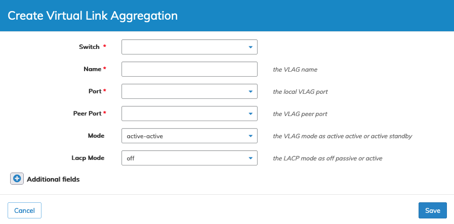
To create a VLAG click Create Virtual Link Aggregation and enter or select the VLAG parameters which include:
•Switch – Select the switch from the drop-down list.
•Name – Enter a suitable name VLAG .
•Port – The local VLAG port.
•Peer-port – The VLAG peer-port.
•Mode – The VLAG mode as active-active or active-standby.
•LACP Mode – The LACP mode as off, passive or active
Manage VLAG Create a VLAG
Click Save to continue or Cancel to return to the previous screen without saving any changes.
Select additional field parameters by clicking on the ![]() icon. Additional fields include:
icon. Additional fields include:
•Lacp Timeout – The LACP timeout as slow or fast.
•Lacp Fallback – LACP fallback mode -- individual or bundled.
•Lacp Fallback Timeout – LACP fallback timeout -- default is 50 seconds.
•Peer Switch – The VLAG peer-switch.
•Failover Move L2 – failover-move-L2 sends gratuitous APRs or not.
•Lacp Port Priority – LACP Port Priority.
Click Save to continue or Cancel to return to the previous screen without saving any changes.
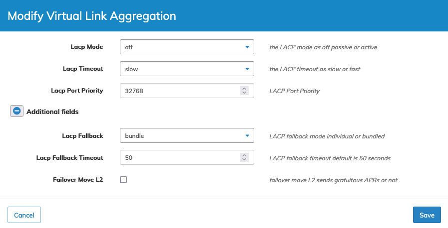
Modify Virtual Link Aggregation
To modify a VLAG click on Edit by selecting the Cog ![]() icon to make changes to the VLAG parameters which include:
icon to make changes to the VLAG parameters which include:
•Lacp Mode – The LACP mode as off, passive or active
•Lacp Timeout – The LACP timeout as slow or fast
•Lacp Port Priority – LACP Port Priority
Select additional field parameters by clicking on the ![]() icon. Additional fields include:
icon. Additional fields include:
•Lacp Fallback – LACP fallback mode -- individual or bundled.
•Lacp Fallback Timeout – LACP fallback timeout -- default is 50 seconds.
•Failover Move L2 – Failover-move-L2 sends gratuitous APRs or not.
Manage VLAG Modify VLAG Parameters
Click Save to continue or Cancel to return to the previous screen without saving any changes.
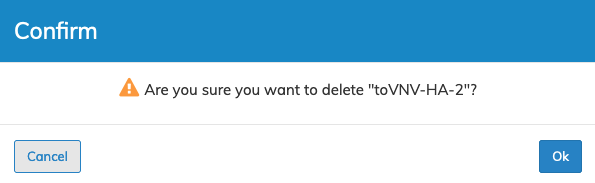
Delete VLAG
To delete a VLAG click on Delete by selecting the Cog ![]() icon.
icon.
Manage VLAG Delete VLAG
Click OK to delete or Cancel to return to the previous screen without making any changes.