
VLAN / L2 OVL - Manage vLE
Layer 2 – Manage vLE - Virtual Link Extension
There are features and functions used in Arista NetVisor UNUM and Insight Analytics that are common throughout the user interface (UI). Please refer to the Common Functions section for more information on the use of these functions and features.
Manage vLE
Selecting Manager → Services → Manage vLE displays the Manage vLE dashboard with a list of any existing vLE settings.
Note: NetVisor UNUM does not currently support theVirtualWire Dashboard in a Super Fabric. NetVisor UNUM supports the Manage vLE function at a Pod level only. Select a Pod from the Left-Hand Navigation (LHN) pane.
A Virtual Link Extension (vLE) is a logical link or tunnel. A vLE connect ports within a switch, or from a port on one switch to a port on a switch in another cluster.
The vLE feature requires that a Layer-3 fabric must be deployed from a NetVisor UNUM Layer-3 Playbook. If you have an existing Layer-3 fabric (i.e. built with the CLI or built prior to NetVisor UNUM) where you wish to use vLE, the VXLAN tunnels will have to be built and configured. Please contact Technical Support.
The workflow in building a vLE involves four basic steps:
Configuration Note: Whenever possible, physically cabling the devices to be connected to their respective ports before creating the vLE simplifies the process.
1)Use Manager → Services → vLE → Manage vLE to create a vLE. To add a vLE click Create Virtual Link Extension. The vLE Connection dashboard opens and you enter the applicable configuration parameters.
oProvide a meaningful name, such as Leaf1p30-L3p30, where the vLE will connect Leaf1, Port 30 to Leaf3, Port30.
oWhen creating the vLE, each requires a unique VLAN and VXLAN identifier, e.g. VLAN 30, VXLAN 10030.
2)Verify the port state is up via the Port Status dashboard (Manager → Layer 1 → PHYSICAL PORTS → Port Status).
3)Complete the connection between devices by cabling both ends of the vLE to their respective devices (unless this was already done).
4)Trigger a vLE discovery from thevLE Overlay (Overlay → Overlay details → Gear button → Trigger vLE discovery).
At this point the vLE inter-link connection in the ring diagram updates reflecting the new vLE connection. Changes in the inter-link visual indicators from Green to Red, or vice versa, indicate whether ports are "up" or down". In either case, the vLE is created and displayed in the dashboard. Bringing the ports "up" and ensuring the Tunnel is "up" changes the vLE status to Up. If the inter-link connection stays Red, please verify that the port(s) state is up and the respective devices are connected and active.
Select the applicable Fabric from the left-hand navigation bar and the dashboard updates showing all vLE entries from all switches within the Fabric.
Note: If no entries exist a "No Data Exists" message is displayed. You must first configure an entry on a switch. Prerequisite settings and configuration may be required.
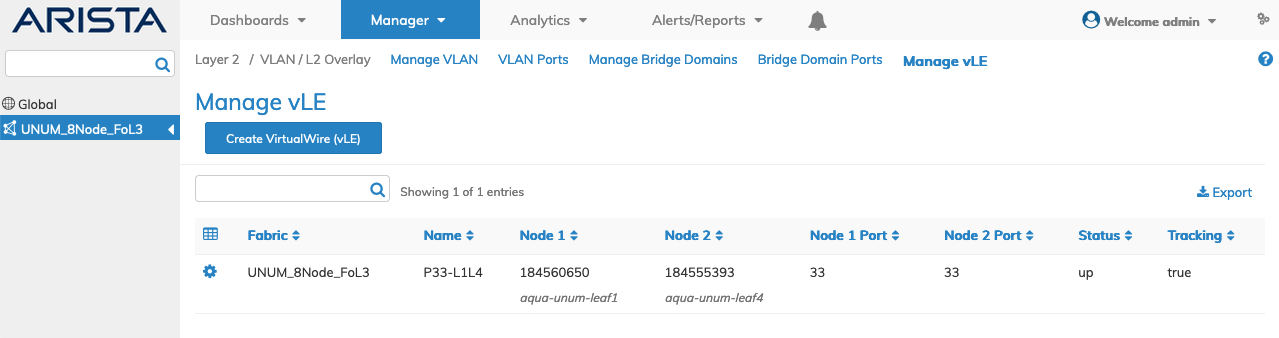
The dashboard displays a list of existing vLE entries by Fabric.
Additional parameters include: Name, Node 1, Node 2, Node 1 Port, Node 2 Port, Status and Tracking.
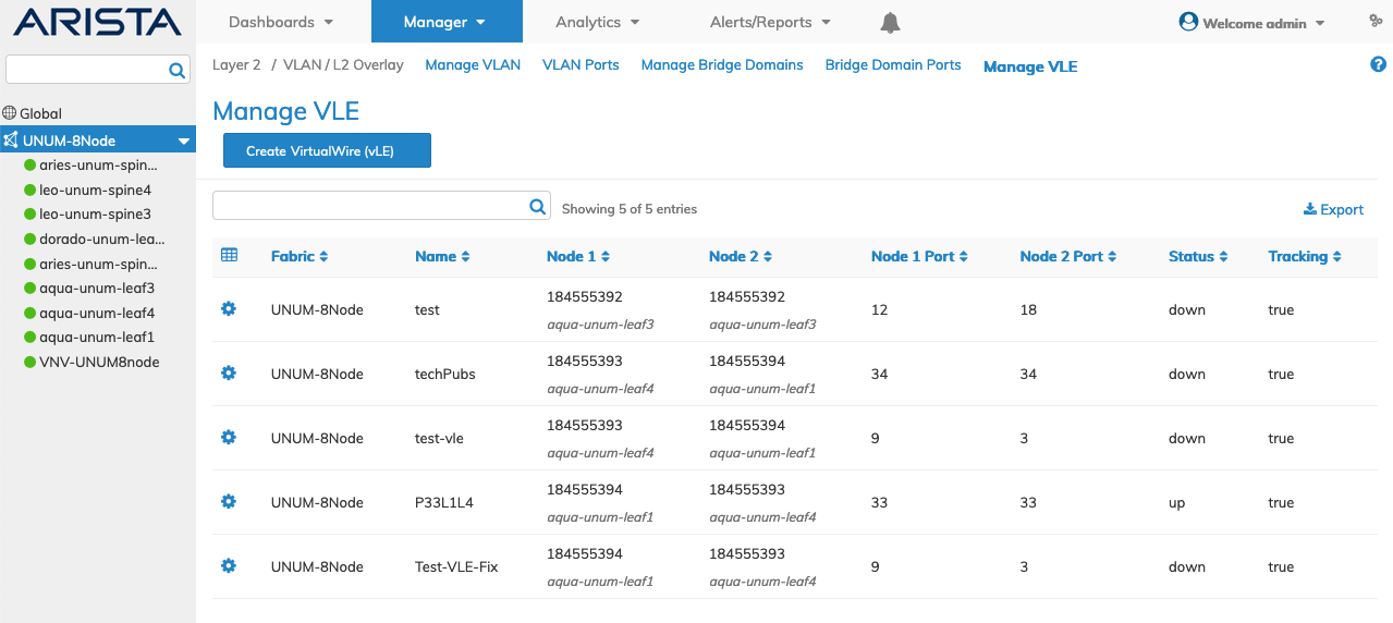
Fabric Manager Services Manage vLE Fabric Dashboard
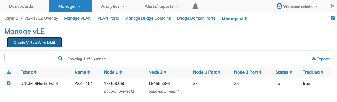
Select the applicable switch from the fabric and the dashboard updates automatically with vLE switch settings by Name.
Additional parameters include: Node 1, Node 2, Node 1 Port, Node 2 Port, Status and Tracking.
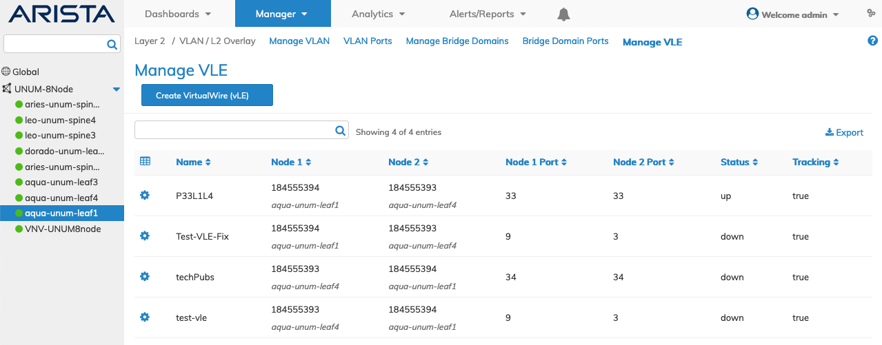
Fabric Manager Services Manage vLE Switch Dashboard
Modify Virtual Link Extension
It can be convenient to manage vLE ports in pairs as a single entity (instead of doing so individually). Starting from NetVisor OS release 6.0.0, use the end-to-end vLE configuration option to enable or disable both vLE ports simultaneously.
To modify a vLE entry use Edit by selecting the Cog ![]() icon to make changes to the vLE configuration which include:
icon to make changes to the vLE configuration which include:
•Tracking – (checkbox) - Enable/disable tracking between vLE ports.
•Port State – (drop-down) - Ports admin control state (override | enable | disable).
•vNET Id – vNET assigned to this vLE.
Port States Option
The new ports-state option has three values:
•Override is the default setting which means that, as usual, each port state configuration takes precedence.
•Disable means that both vLE ports get disabled together, and this option takes precedence over each port state.
•Enable means that both vLE ports get enabled, and this option takes precedence over each port state.
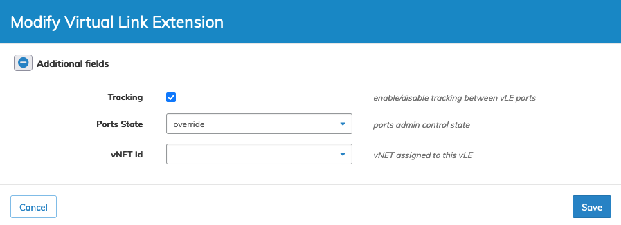
Manage Services Manage vLE - Modify vLE
Click Save to continue or Cancel to return to the previous screen without saving any changes.
Create VirtualWire
vLEs are added by selecting Create VirtualWire (vLE).
Fabric Manager Services Manage vLE - Create Virtual Link Extension Tracking
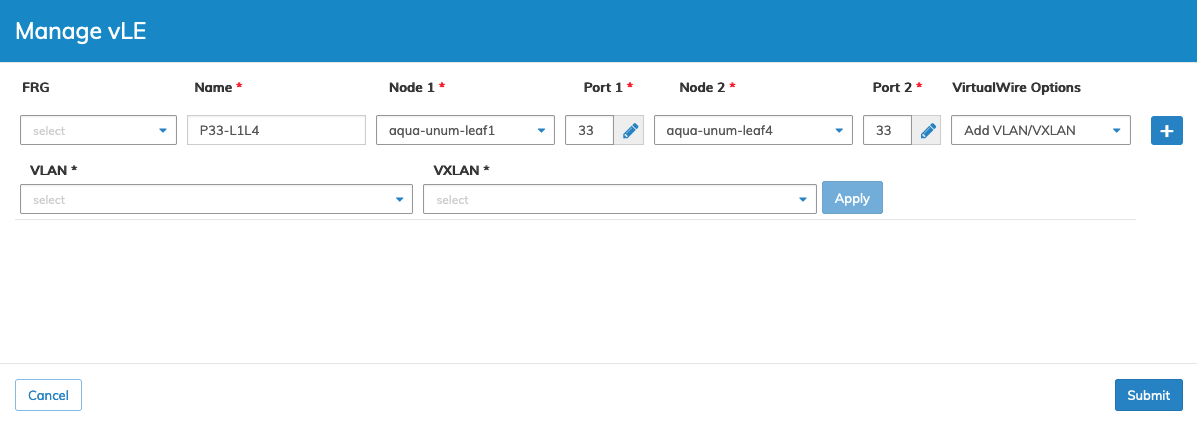
Enter the configuration parameters which include:
•FRG – Fabric Resource Group.
•Name – (required) - vLE name
•Node 1 – (required) - vLE node 1
•Node 2 – (required) - vLE node 2
•Port 1 – (required) - Node-1 port of vLE
•Port 2 – (required) - Node-2 port of vLE
•VLAN – (required) VLAN number
•VXLAN – (required) - VXLAN number
Click the ![]() icon to add the vLE. Repeat the process to add more vLE entries. Click Apply to complete the entry.
icon to add the vLE. Repeat the process to add more vLE entries. Click Apply to complete the entry.
Submit to continue or Cancel to return to the previous screen without saving any changes.
The vLE is added to the vLE Dashboard.
Fabric Manager Services Manage vLE - vLE Added to Dashboard
The new vLE appears in the dashboard. If the tunnel and selected ports are "up" the Status will appear as up. Otherwise the Status shows down.
In this event ensure the ports are physically connected to the switch and the tunnel is functioning. When these conditions are met the dashboard updates accordingly.
Fabric Manager Services Manage vLE - vLE Added to Dashboard - Status Up
Select Dashboards → Overlay to review the added vLE.
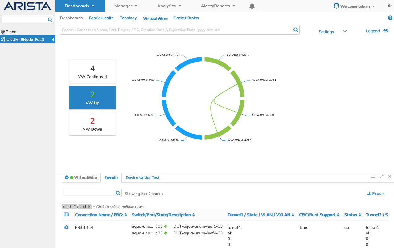
Overlay Dashboard - vLE Added to Dashboard - Status Up
Delete a vLE
To delete a vLE entry use Delete by selecting the Cog ![]() icon. A confirmation message requires an acknowledgment to continue deletion.
icon. A confirmation message requires an acknowledgment to continue deletion.
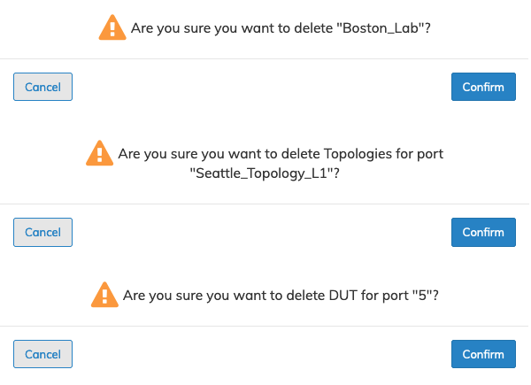
Fabric Manager Services vLE - Delete Entry
Click OK to continue or Cancel to return to the previous screen without making any changes.
Adding a Port Description
To add a description to these ports select Manager → Layer 1 → Manage Ports
Follow the steps as outlined in VirtualWire.