
Virtual Topology - Manage Topology
Virtual Link Extension (vLE) Topology
Using the vLE feature in lab automation deployments requires repeatability when deploying the same topology. For example, there is a need to configure different vLE connections and then save them from being re-created when needed.
Before the NetVisor OS release 7.0.0, the software only supported saving and replaying individual configurations. However, this process is not optimal and convenient for vLE setups because it saves entire switch configurations and restarts the devices.
Starting with NetVisor OS release 7.0.0, a new vLE topology feature automates the creation of vLEs, their associated transparent VLANs, and the associated VXLAN IDs on the tunnels in a convenient and user-friendly fashion. This new functionality introduces a feature whereby users can easily save and replay their topologies without restarting the devices.
The feature’s logic checks for the presence of the static VXLAN tunnel(s) needed between the vLE nodes and displays a warning if they are not active and the automation does not proceed. Conversely, if the tunnels required for vLE creation are present, the automation process adds the required VXLAN ID to each tunnel, creating the vLE setup.
The feature’s logic uses automatic assignment for parameters that are not specified and uses a dry run process to verify potential conflicts. The software checks:
•Ports for conflicts during vLE creation.
•VLAN and VXLAN IDs to see if they are already in use.
•The tunnels required for the vLE functionality.
Note: Only static tunnels are supported, auto-tunnels are not supported. Only single fabric deployments are supported.
Fabric Layer 1 – Virtual Topology - Manage Topology
There are features and functions used in Arista NetVisor UNUM and Insight Analytics that are common throughout the user interface (UI). Please refer to the Common Functions section for more information on the use of these functions and features.
Manage Topology
Please refer to the Packet Broker and VirtualWire sections for more information about vPGs.
Selecting Manager → Layer 1 → Virtual Topology → Manage Topology displays the Manage Topology dashboard with a list of any existing Topology entries.
Select the applicable Fabric from the left-hand navigation bar and the dashboard updates showing all Topology entries from all switches within the Fabric.
Note: If no entries exist a "No Data Exists" message is displayed. You must first configure an entry on a switch. Prerequisite settings and configuration may be required.
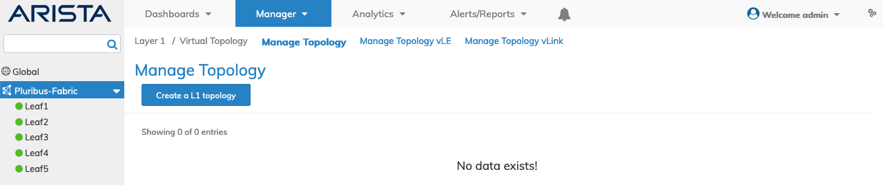
Manager Virtual Topology - Manage Topology - Fabric Dashboard - No Topologies
Create a Layer 1 Topology
Using Create a L1 topology, select a Switch from the drop-down list, enter the requisite parameters, which include:
•Switch – Select a Switch.
•Name – The name assigned to the Topology.
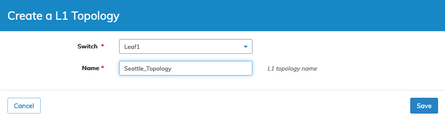
Manager Virtual Topology - Manage Topology - Create a Topology
Click Save to continue or Cancel to return to the previous screen without making any changes.
The function has a fabric scope, meaning the topology builds on all switches in the Fabric.
The dashboard updates with the new L1 topology.
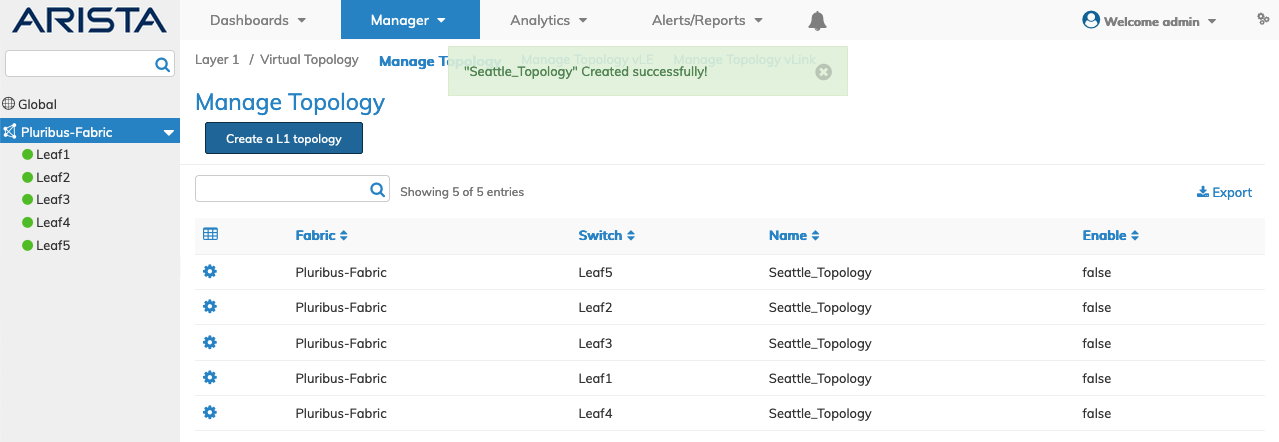
Manager Virtual Topology - Manage Topology - New L1 Topology
Note: The virtual topology is initially disabled.
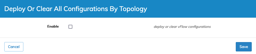
Select an entry and enable a topology using the Cog ![]() icon and checking Enable.
icon and checking Enable.
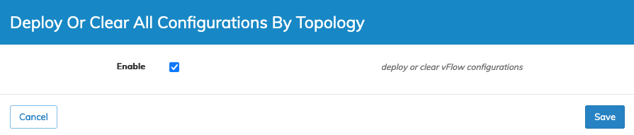
Manager Virtual Topology - Manage Topology - Deploy the vFlow
Click Save to continue or Cancel to return to the previous screen without making any changes.
The dashboard updates and the topology enabled.
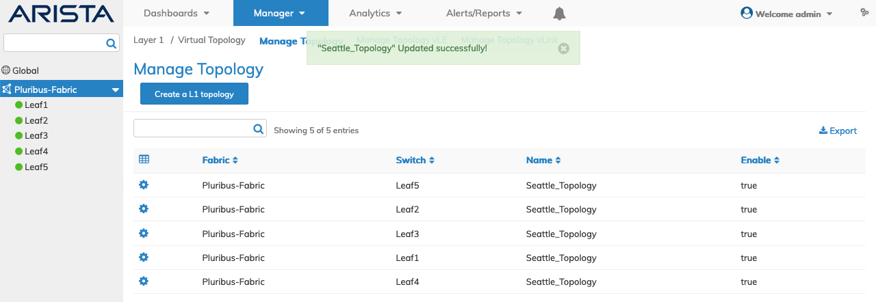
Manager Virtual Topology - Manage Topology - Enable
Multiple virtual topologies can co-exist at any time.
The dashboard displays a list of existing Topology entries by Fabric and Switch.
Additional parameters include: Name, and Enable.
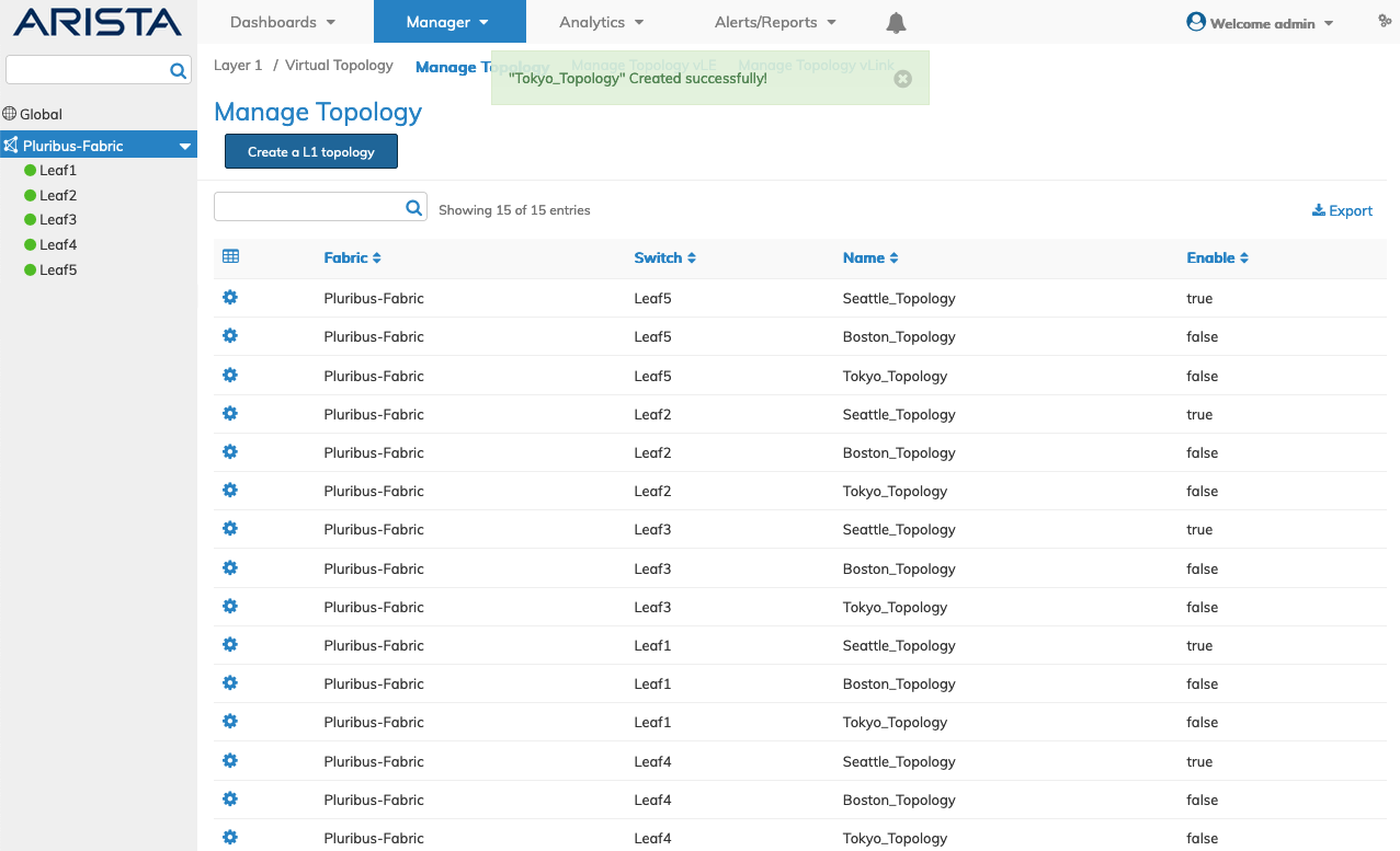
Manager Virtual Topology - Manage Topology - Multiple Virtual Topologies
Delete a Virtual Topology
You must first disable a topology to delete the topology.
Select Edit using the Cog ![]() icon and disable the topology. Click Save to continue.
icon and disable the topology. Click Save to continue.
Manager Virtual Topology - Manage Topology - Disable Topology
Select Delete using the Cog ![]() icon and delete the topology. Confirm the deletion.
icon and delete the topology. Confirm the deletion.
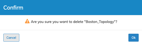
Manager Virtual Topology - Manage Topology - Delete Topology
Proceed to Manage Topology vLE to add a vLE to a virtual topology.