
Add Fabric
Add Fabric Seed Switch
There are features and functions used in Arista NetVisor UNUM and Insight Analytics that are common throughout the user interface (UI). Please refer to the Common Functions section for more information on the use of these functions and features.
NetVisor UNUM Add Fabric
To add a Fabric and begin the NetVisor UNUM configuration process, right-click on Global and select the Add Fabric icon or select Manager → Fabric → Add Fabric.
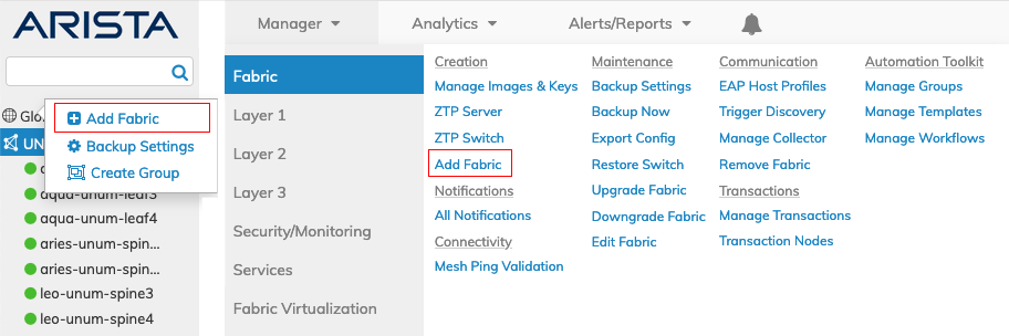
NetVisor UNUM Topology Left-hand Navigation - Add Fabric Menus
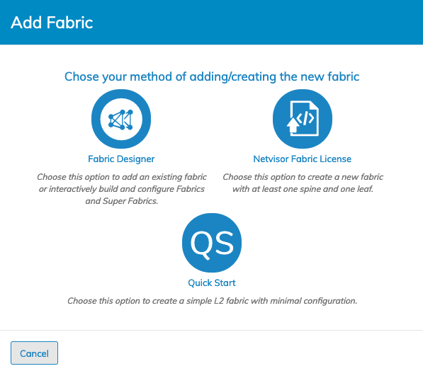
Select the applicable Fabric create option.
NetVisor UNUM Platform Global - Add Fabric
Fabric Create Options
Select the Add Fabric option based on the type of fabric you want to add or create:
Fabric Designer – add an existing fabric via a seed switch.
Netvisor Fabric License – create a new fabric with at least one spine and one leaf.
Quickstart – Create a simple L2 Fabric with minimal configuration.
Note: Users can configure multiple Fabrics in parallel after completing an initial configuration. While the first Fabric is being created/discovered you launch another Fabric creation process by clicking on the applicable Fabric icon as shown above.
Fabric Designer
Fabric Designer provides an easy-to-use interactive configuration process for adding an existing Fabric to your NetVisor UNUM instance.
Use Fabric Designer to add an existing fabric and build a new Fabric from scratch. As mentioned below, building a Fabric from scratch is EFT and should be limited to eight devices. Adding an existing fabric to create a Super Fabric with up to 32 nodes in each Fabric is fully supported.
Caution: Fabric Designer is an Early Field Trial (EFT) feature for designing certain types of Fabrics. EFTs are intended for test environments and are not supported for use in production networks. You should consult your local partner or Arista Networks account team before using any EFT feature or to provide feedback.
Arista Networks recommends limiting new Fabric creation to 8 nodes or less as you may experience overlapping situations creating larger fabrics.
Note: Adding existing Fabrics via the Seed Switch option is fully supported in Fabric Designer.
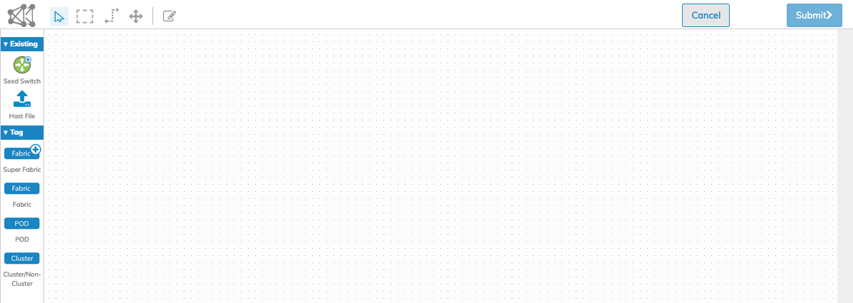
Click the Fabric Designer icon to add an existing Fabric.
![]()
NetVisor UNUM Platform Global - Fabric Designer
NetVisor UNUM Platform Global - Fabric Designer User Interface & Planning Surface
User Interaction
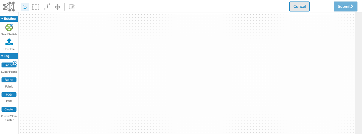
The Fabric Designer UI contains various sections allowing the user to quickly design and create Fabrics, Pods, Super Fabrics, and their associated inter-connectivity.
Fabric Designer contains the Planning Surface, Icons & Tags, Tools, Header, Fabric Controls, and Form Editor.
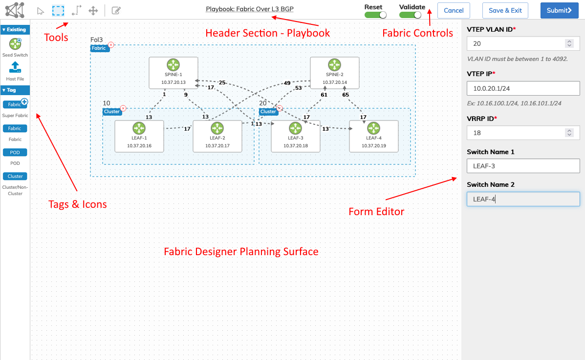
NetVisor UNUM Platform Global - Fabric Designer User Interaction
Icons and Tags
|
Drag and drop the appropriate icon or tag onto the planning surface. •Seed Switch – Specify a Seed Switch for use in a Fabric, Super Fabric or Pod. Use the Seed Switch icon to add an existing Fabric. •Fabric Plus – Create a Super Fabric using multiple Fabrics. •Fabric – Create a Fabric containing Spines, Leafs, and Switch Clusters. •POD – Create a Pod containing multiple nodes. •Cluster – Create a switch cluster using two nodes. |
Fabric Designer - Icons and Tags Menu |
|
Note: When using the ZTP Switch feature to ONIE or PXEBoot switches or DPUs and selecting the Generate Fabric function, a host file is created and automatically populates the Fabric Designer with the specific switch and DPU details. In this case, uploading a host file is not required. |
|
Tools
|
Use the appropriate tool to create groups, interface links and move nodes on the planning surface. |
Fabric Designer - Tools Menu |
|
•Cursor Tool – Select a node, group, or Fabric. |
|
|
•Group Tool – Create a group of nodes to specify a Super Fabric, Fabric, Pod, or Cluster. |
|
|
•Interface Links Tool – Draw interface links between nodes. |
|
|
•Move Node Tool – Move nodes on the planning surface. |
|
|
•Draft Tool – Retrieve and manage an unpublished design for further edits. Refer to the Save & Exit section for further details. |
|


Header
|
•Playbook – Specifies the Playbook used to create the Fabric. |
Fabric Designer - Header - Playbook Example |

Fabric Controls
|
Controls for configuring Fabrics. •Reset – Resets existing Leaf and Spine switches or DPUs. •Validate – Evaluates the initial Fabric build as a check to ensure NetVisor UNUM can deploy the playbook. •Cancel – Cancel the current operation and return to the previous menu. •Save & Exit – Save an unpublished design for subsequent editing. Refer to the Save & Exit section for further details. •Submit – Submit the configuration for creating the Fabric, Super Fabric or Pod. |
Fabric Designer - Fabric Controls |

Form Editor
|
Use to form editor to enter specific parameters for configuring nodes, clusters, Fabrics, Pods, and Super Fabrics. The form editor parameters change depending on the requirement when configuring an item. |
Fabric Designer - Form Editor - Cluster Configuration Example |
Fabric Designer - Create Fabric over Layer 3 with BGP and Switch Clustering
The following section illustrates an example of using Fabric Designer to create a Fabric over Layer 3 with BGP.
The model assumes each switch (node) was ONIE provisioned and has NetVisor OS installed on each node and physical cable connections are in place between each node.
Note: Input parameters fields in the Form Editor fields may vary depending on the specific design chosen during the configuration process. The examples shown below may not match your exact setup.
1)Launch the Fabric Designer.
Fabric Designer - Blank Planning Surface
2)Create a host file with the required switch settings.
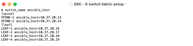
Fabric Designer - Host File Settings
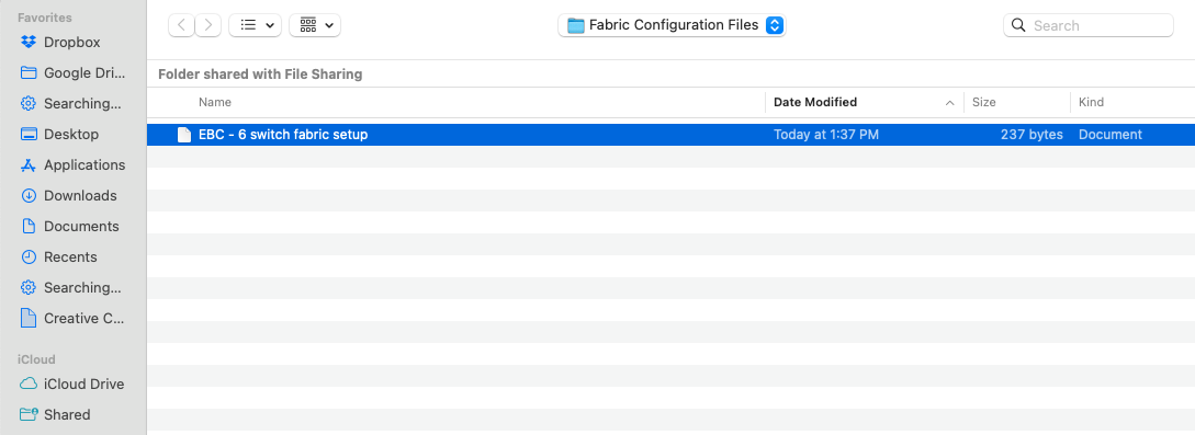
3)Click the Host File button and select the required host file and upload.
Fabric Designer - Upload Host File
4)The Fabric Designer planning surface displays the nodes.
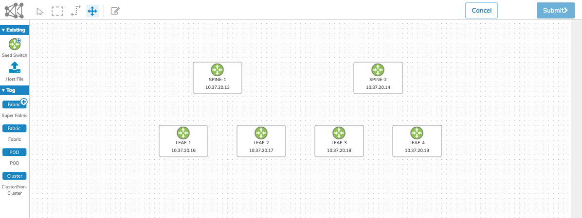
Fabric Designer - Nodes Loaded
5)Use the Cursor Tool to select each node to review the individual node settings. Enter the required information or make any changes as required.
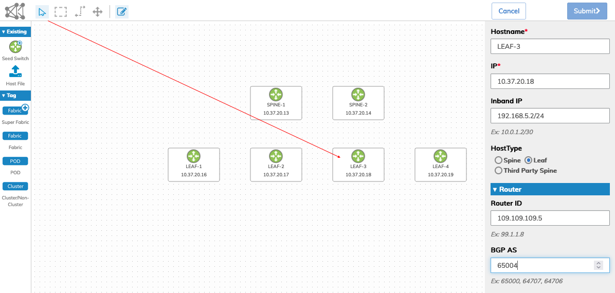
Fabric Designer - Node Details
6)Group the nodes using the Group Tool.
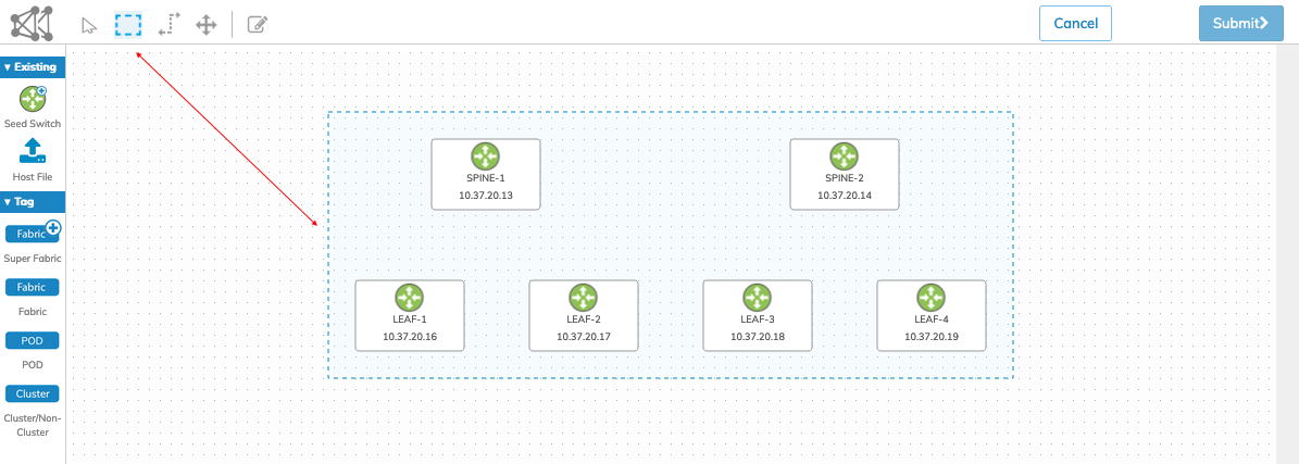
Fabric Designer - Nodes Loaded
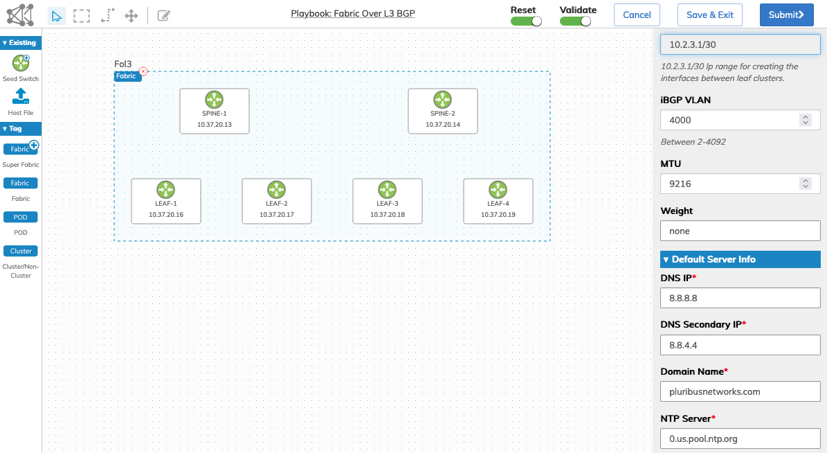
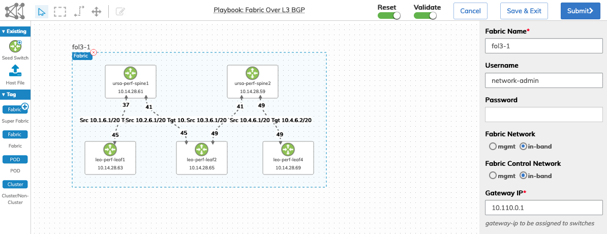
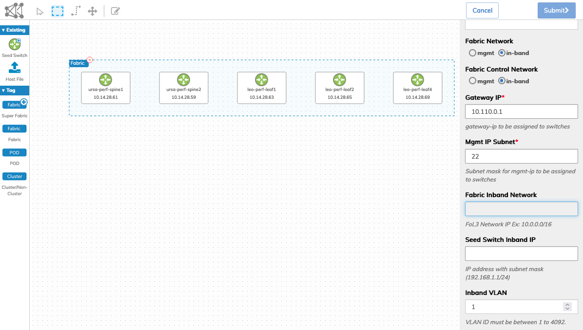
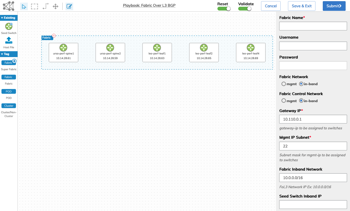
7)Drag and drop the Fabric icon into the highlighted group and enter the required information using the Form Editor.
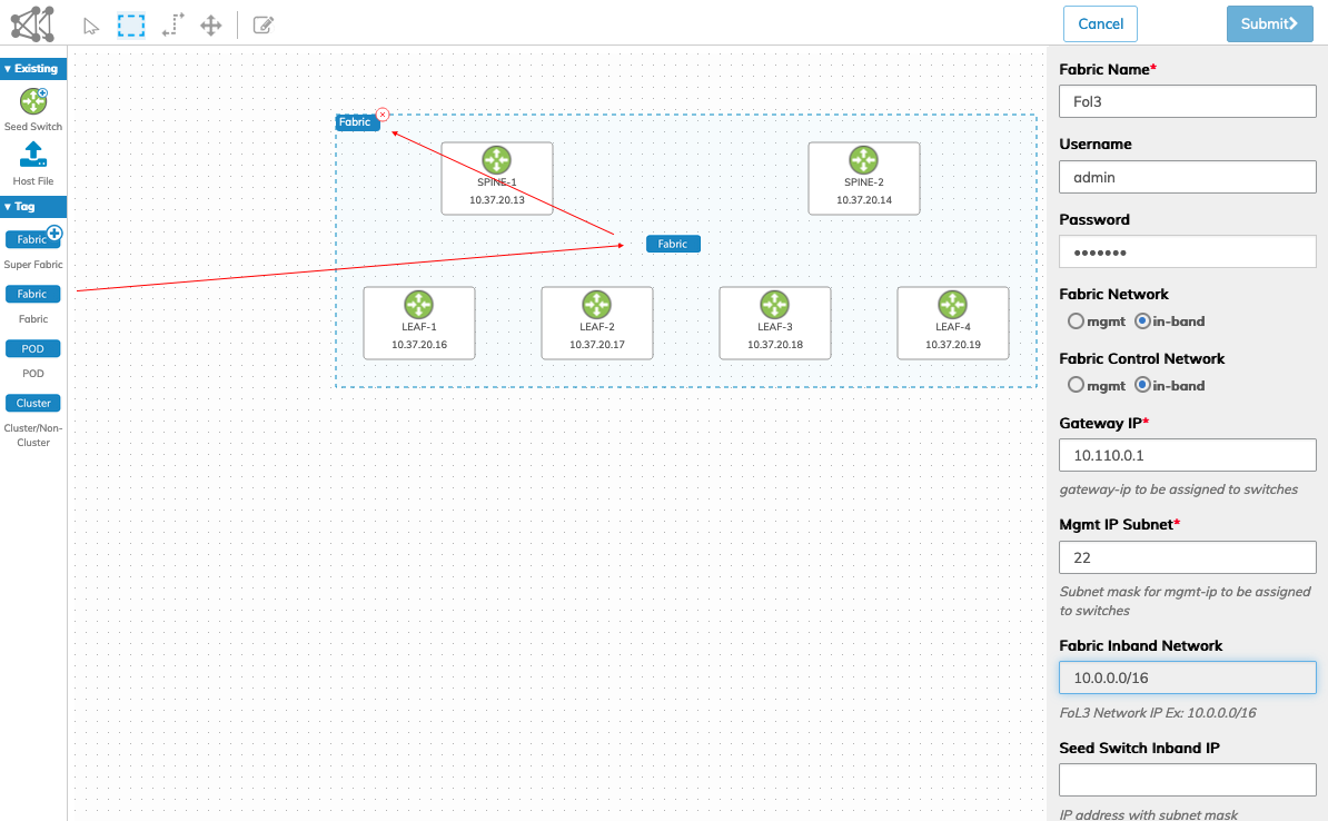
Fabric Designer - Designate Fabric
8)Enter all required parameters for the Fabric. Selecting In-band for Fabric Network and Fabric Control Network loads the Fabric over Layer 3 BGP Playbook, which displays in the header. Fabric control buttons, Reset and Validate, are enabled by default.
In this example, using the following settings determines the use and execution of the Fabric over Layer 3 BGP Playbook.
•Fabric Network = Inband
•Fabric Control Network = Inband
•Fabric Inband Network = 10.0.0.0/16 - required for FoL3 Network
Fabric Designer - Enter Fabric Parameters - Playbook Displayed
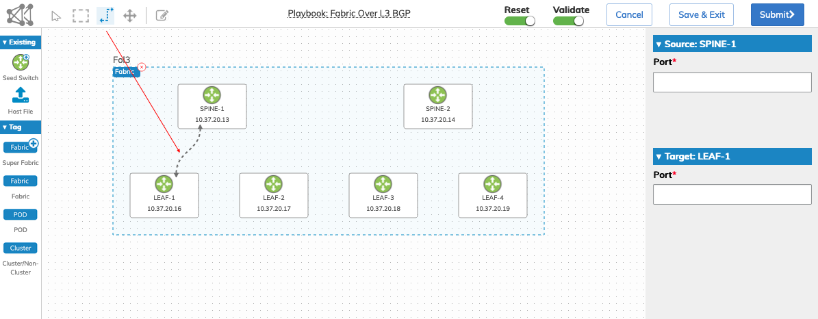
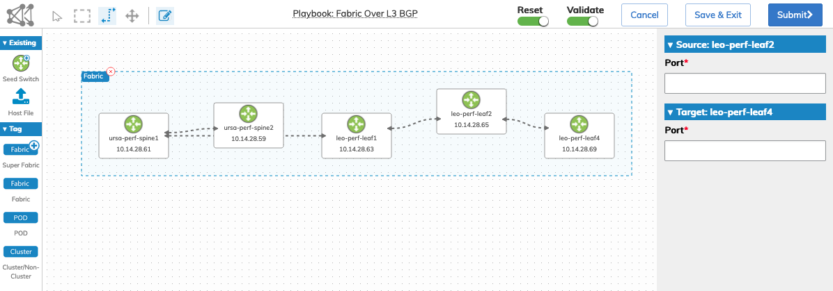
9)Use the Links Tool to create the links between the nodes. Enter the applicable port numbers in the Form Editor. The port numbers are the physical connected ports on each node.
Fabric Designer - Enter Links
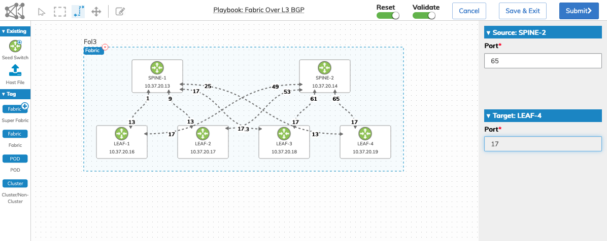
10)Repeat the process using the Link Tool and the Form Editor, entering all required links.
Fabric Designer - All Links Entered
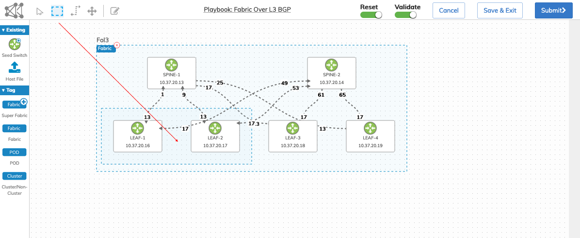
11)Use the Group Tool to highlight the two nodes required for each switch cluster.
Fabric Designer - Highlight Cluster Nodes
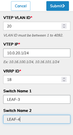
12)Drag and drop the Cluster Tag into the highlighted node group and enter the required cluster configuration parameters in the Form Editor.
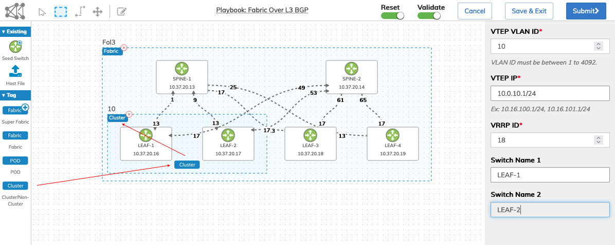
Fabric Designer - Enter Cluster Parameters
13)Repeat steps 11 and 12 to complete the configuration of the second switch cluster.
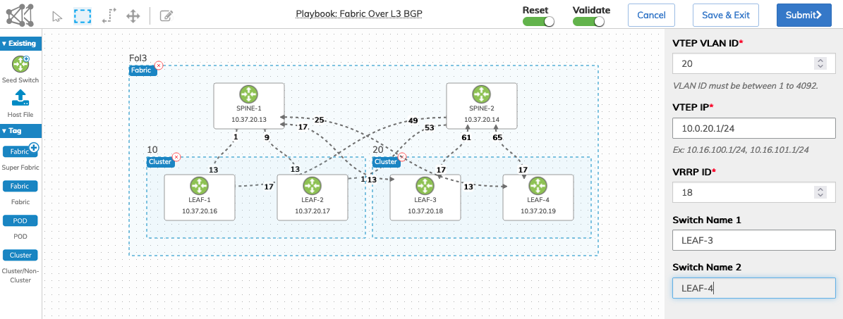
Fabric Designer - Cluster Configurations Complete
14)Verify the Fabric configuration and enter any corrections as required. Save an unpublished design using the Save & Exit function. See the Save & Exit section for further information.
Note: Submitted designs are considered "published" and cannot be retrieved using the Draft tool.
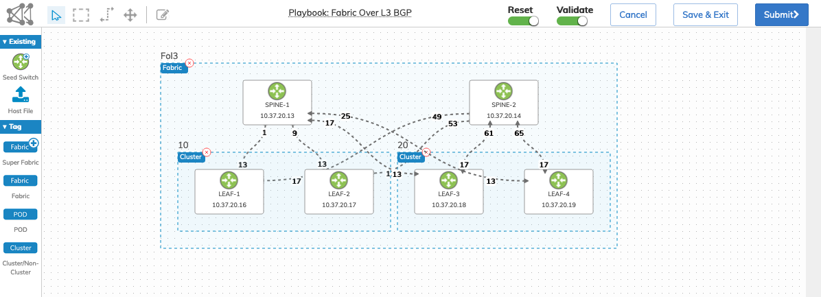
Fabric Designer - Fabric Configuration Complete
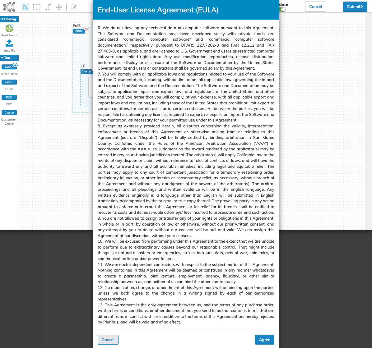
15)Click Submit to continue or Cancel to return to the previous screen without making any changes. Accept the EULA by clicking Agree.
Fabric Designer - EULA Accept
16)The ZTP process begins, and the Playbook launches.
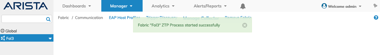
Fabric Designer - ZTP Process Message
17)The Topology dashboard displays the status in the blue progress bars in the Details pane. The Topology map displays node status.
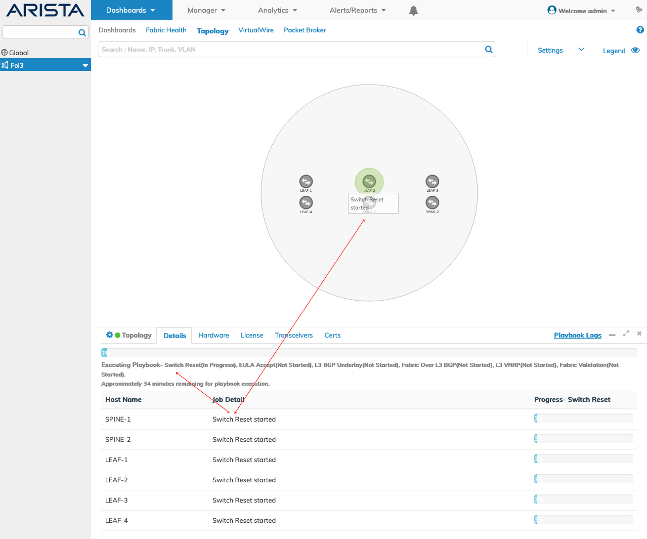
Fabric Designer - Playbook Progress Bars and Status Messages
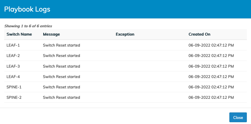
18) Select Playbook Logs at any time during the configuration process to review specific details of the Playbook process.
Fabric Designer - Playbook Logs
19)The process runs until the Playbook finishes and the Topology map displays a series of messages. Click Cancel to remove the pop-up message.
Note: The following screenshot is an example for illustrative documentation purposes only. The messages may appear at different times.
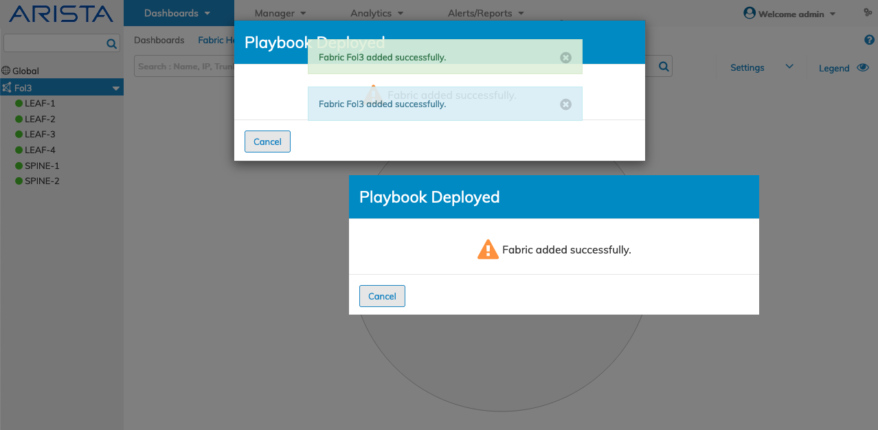
Fabric Designer - Playbook Deployed Messages
20) After the discovery process runs the Topology dashboard displays the new Fabric.
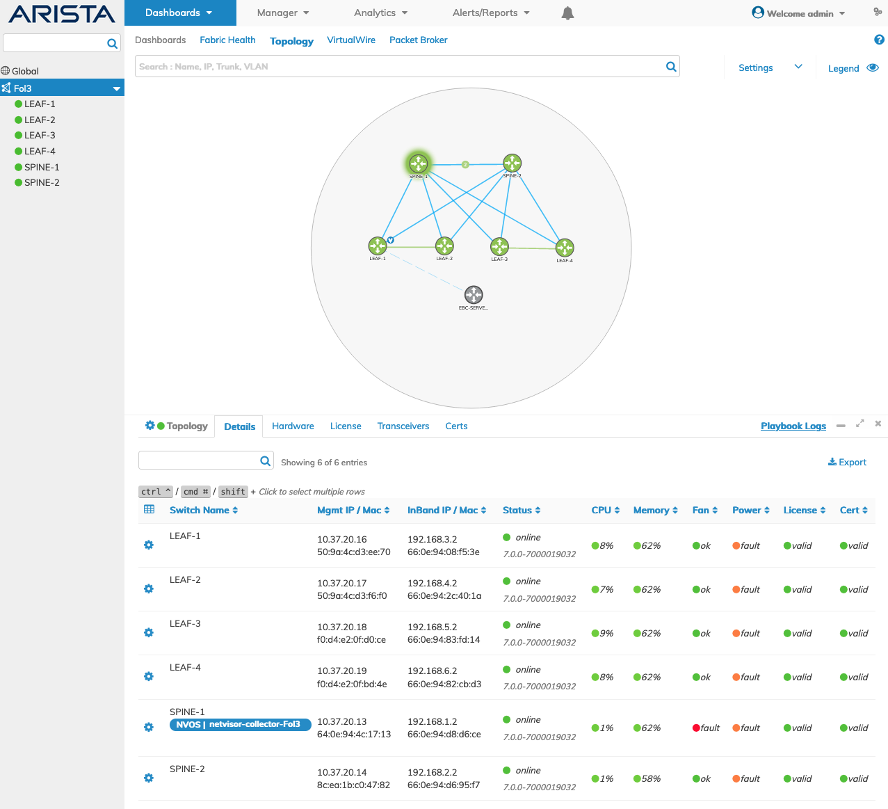
Topology Dashboard - Fabric Created
Save and Exit
The Save & Exit function allows you to save and retrieve a design for later editing and appears after a Playbook is ready for execution.
Fabric Designer - Save Configuration
In the following example, uploading a host file and using the Group tool to designate a Fabric displays the fabric configuration Form Editor.
Fabric Designer - Save Configuration - Form Editor
After entering sufficient information to configure the Fabric, the Save & Exit button appears.
At this point, the design can be saved and retrieved at a later time.
Click Save & Exit to end the configuration process, if desired. The configuration is saved and stored internally. Since the design was not submitted, it is considered "unpublished" and available for further editing.
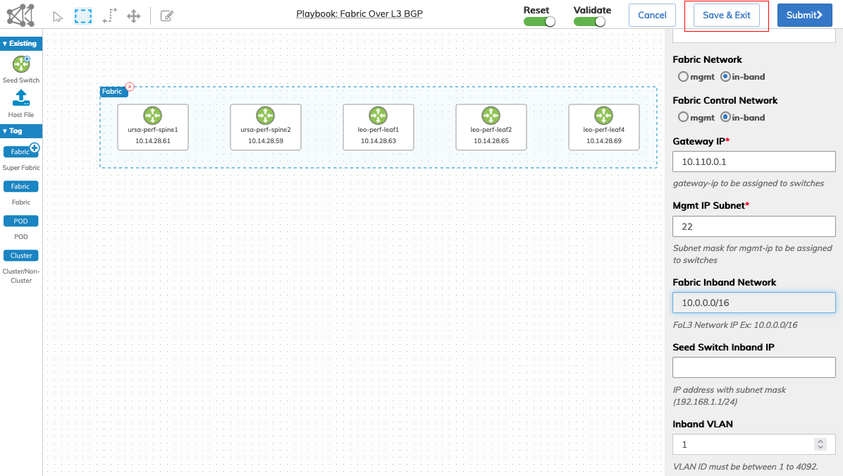
Fabric Designer - Save & Exit - Example
To manage and retrieve the unpublished configuration, return to the Fabric Designer. When a design is available for further edits, the Draft tool is enabled (highlighted in blue).
Fabric Designer - Draft Button Enabled
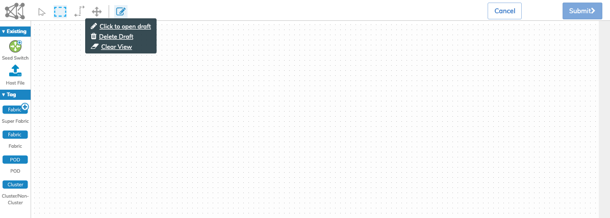
Draft Tool Menu
•Click to Open Draft: After saving a draft, Click to open draft retrieves that draft.
•Delete Draft:
1)Delete an existing draft.
2)Delete Draft prompts with Confirmation pop-up "Delete will clear all saved config and close the designer window.
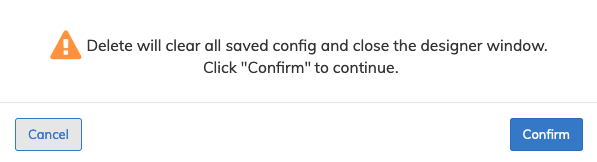
3)Click Confirm to continue or Cancel to return to the previous screen without making any changes.
•Clear View: Clear the current draft view to create a new configuration.
Note: There is no file management built into the Fabric Designer. UNUM saves only a single draft at any one time. To create a new configuration draft, delete the existing Draft and start again. Submitted designs are no longer considered drafts and cannot be retrieved using the Draft tool.
Click the Draft tool and the retrieved design appears in the planning surface.
Fabric Designer - Retrieved Design
Make further edits as required and use the Save & Exit function as needed until submitting the design to create the Fabric using the Submit button.
Fabric Designer - Additional Edits
Execution Failed During Fabric Creation
If the Playbook fails to achieve a successful Fabric creation process, the following error message example describes particular reasons why the operation failed.
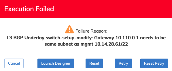
Fabric Designer - Playbook Error Message Example
Several options exist to rectify the condition, including:
•Launch Designer – Launch the Fabric Designer to edit the configuration and re-run the setup.
•Reset – Reset existing Leaf and Spine switches or DPUs.
•Retry – Re-run the Playbook with the existing settings.
•Reset Retry – Reset existing Leaf and Spine switches or DPUs and then re-run the Playbook with the existing settings.
•Cancel – Cancel the current operation and return to the previous menu.
Note: After an Execution Failed scenario, use the Fabric Designer (Launch Designer) to make changes to rectify the issue using the Form Editor. However, since the design is "published," the Draft tool button is disabled.
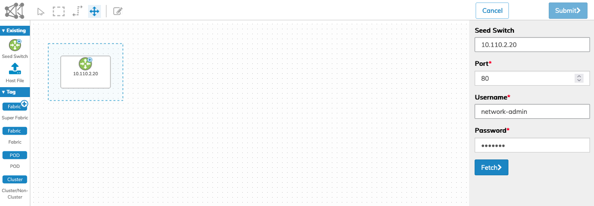
Existing Seed Switch
To create a Fabric using an existing Seed Switch, drag and drop the Seed Switch icon on to the planning surface. Enter the Seed Switch name or IP address, the applicable control Port (default is port 80), and the User Name and Password.
After entering the required information, click Fetch to begin the process.
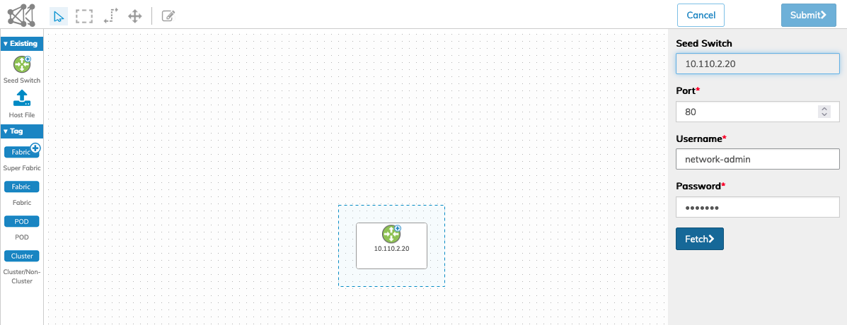
NetVisor UNUM Platform Global - Fabric Designer User Interface Seed Switch Example
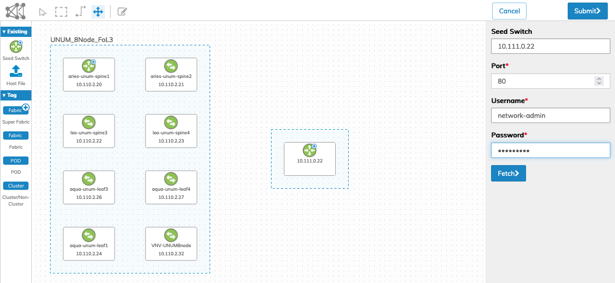
After entering the required information, click Fetch to begin the process.
After a short period and if the seed switch is detected and authorization occurs, the planning surface updates with the seed switch and associated switch details.
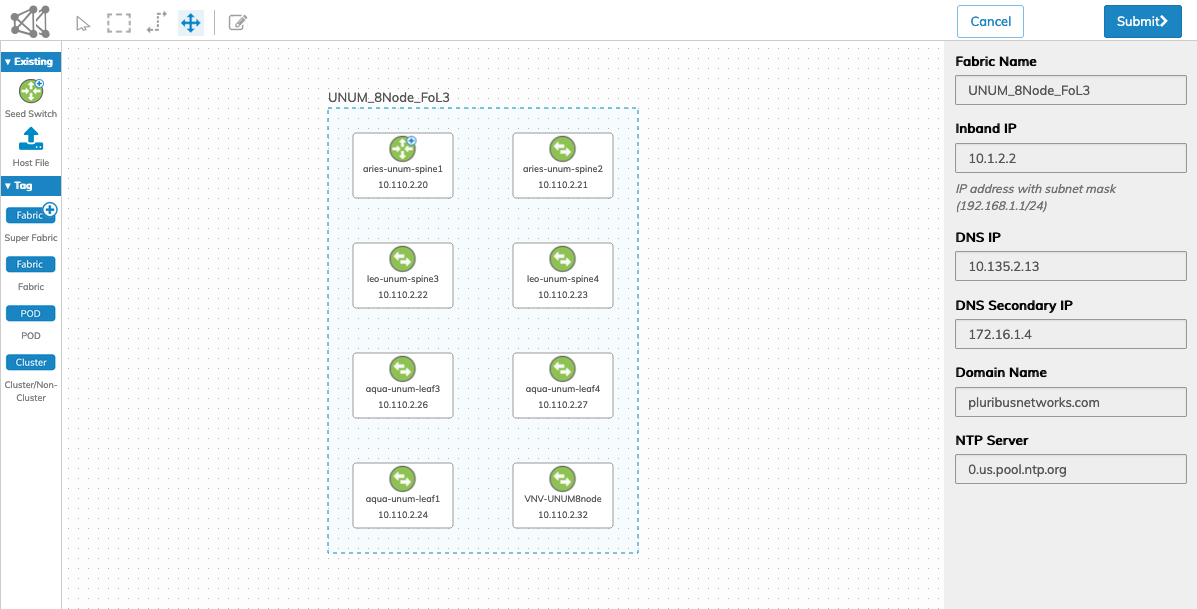
NetVisor UNUM Platform Global - Fabric Designer User Interface Fabric Displayed
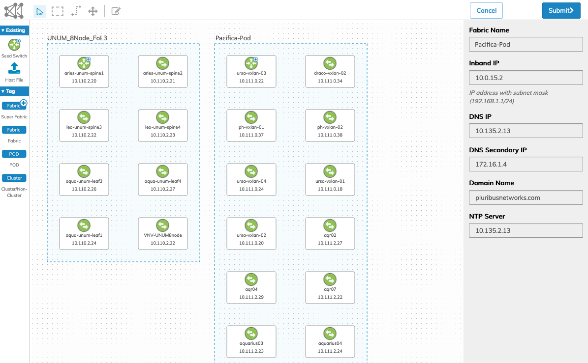
The details of the Fabric Name, Inband IP Address, DNS Settings, Domain Name, and NTP Server are displayed.
Click Submit to continue or Cancel to return to the previous screen without making any changes.
The NetVisor UNUM Dashboard displays a message confirming a successful add of the new seed switch. Conversely, a warning message is displayed should the seed switch fail to be added. You should review all configuration parameters and try again in this event.
The Topology map updates with the added Fabric.
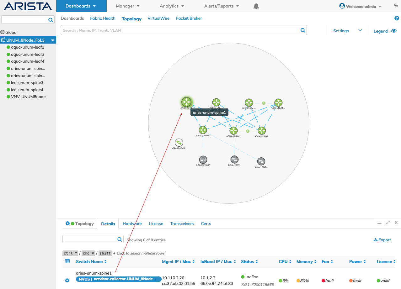
NetVisor UNUM Platform Global - Fabric Added - Topology Updated
Please refer to the Topology section for more information about feature and functions of the Topology Dashboard.
Note: NetVisor UNUM automatically creates a default collector titled netvisor-collector-fabricname when the Fabric is created. View and manage the Collector selecting Manager → Manage Collector. A Syslog entry is also created at the same time. View and manage the Syslog selecting Manager → Security/Monitoring → Manage Syslogs.
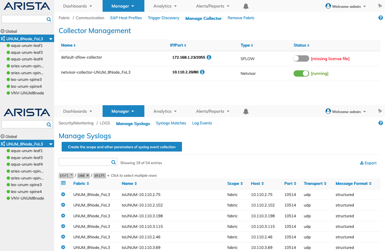
NetVisor UNUM Platform Global - New Seed Switch Collector & Syslog Example
Please refer to the Topology section for more information about feature and functions of the Topology Dashboard.
Super Fabrics
A Super Fabric expands the maximum number of switches from 32 to 140 using four pods. We use the concept of Pods, with each pod containing up to a maximum of 32 switches.
Refer to the EVPN - Symmetric IRB & Super Fabrics Use Case for detailed information on the use of EVPN.
Concepts and Terminology Used in Super Fabrics
Terminology
•Local – A subnet is deemed Local to a POD if it’s only configured on that POD.
•Remote – A subnet is deemed Remote if it’s not LOCAL on that POD.
•Stretched – A subnet is deemed Stretched if it’s present on two or more PODs.
•IRB – Integrated Routing and Bridging
•EVPN – VXLAN Ethernet VPN
•VRF – Virtual Routing and Forwarding
•VNI – VXLAN Network Identifier
Create a Super Fabric
Note: The following is an example and does not represent the actual total maximum capacity of a Super Fabric.
To create a Super Fabric, drag and drop a Seed Switch for each pod on to the planning surface.
NetVisor UNUM Platform Global - Fabric Designer - Create Super Fabric
Enter the first Seed Switch name or IP address, the applicable control Port (default is port 80), and the User Name and Password.
After entering the required information, click Fetch to begin the process.
After a short period and if the seed switch is detected and authorization occurs, the planning surface updates with the seed switch and associated switch details.
NetVisor UNUM Platform Global - Fabric Designer - Create Super Fabric Pod 1
The details of the Fabric Name, Inband IP Address, DNS Settings, Domain Name, and NTP Server are displayed.
Repeat these steps for the second Seed Switch.
NetVisor UNUM Platform Global - Fabric Designer - Create Super Fabric Pod 1 & Pod 2
The details of the Fabric Name, Inband IP Address, DNS Settings, Domain Name, and NTP Server are displayed.
As is the case of a standard Fabric, to edit the switch (hostname), IP, and HostType settings, click on a device in the particular Fabric planning surface. The Fabric window resizes when you move and rearrange the devices on the planning surface.
Drag and drop the Super Fabric icon on to the planning surface.
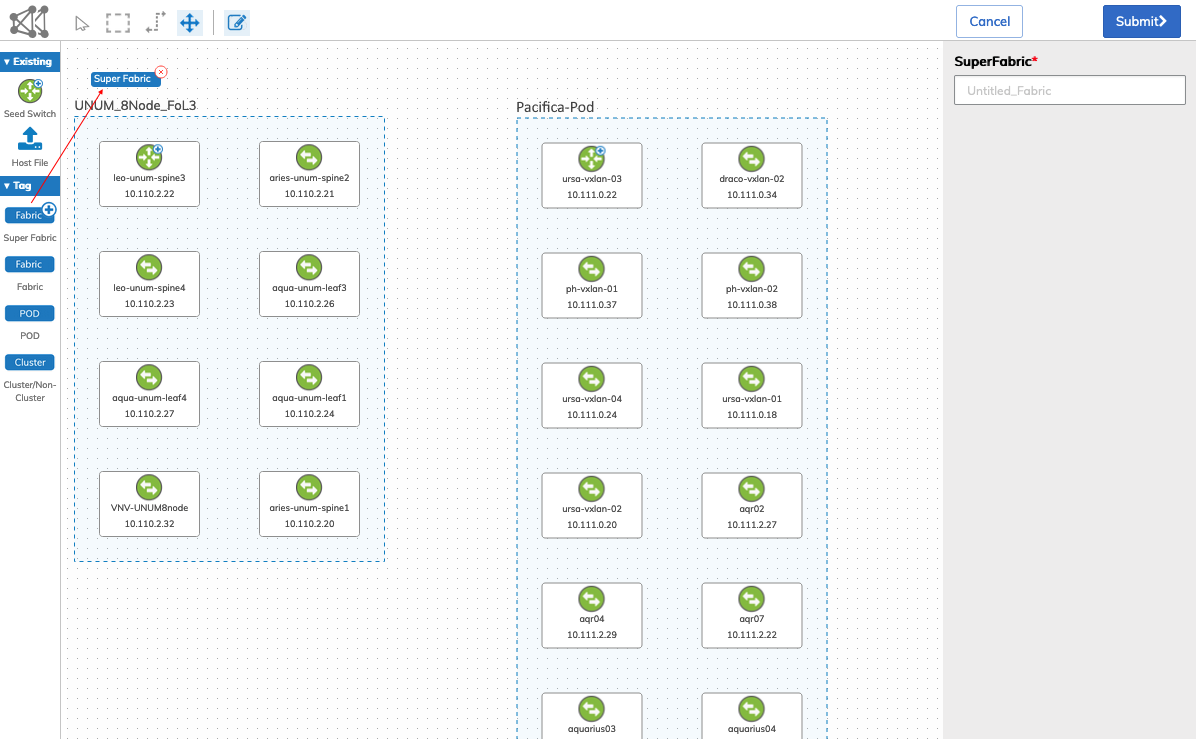
NetVisor UNUM Platform Global - Fabric Designer - Group Pod 1 & Pod 2
Enter a name for your Super Fabric.
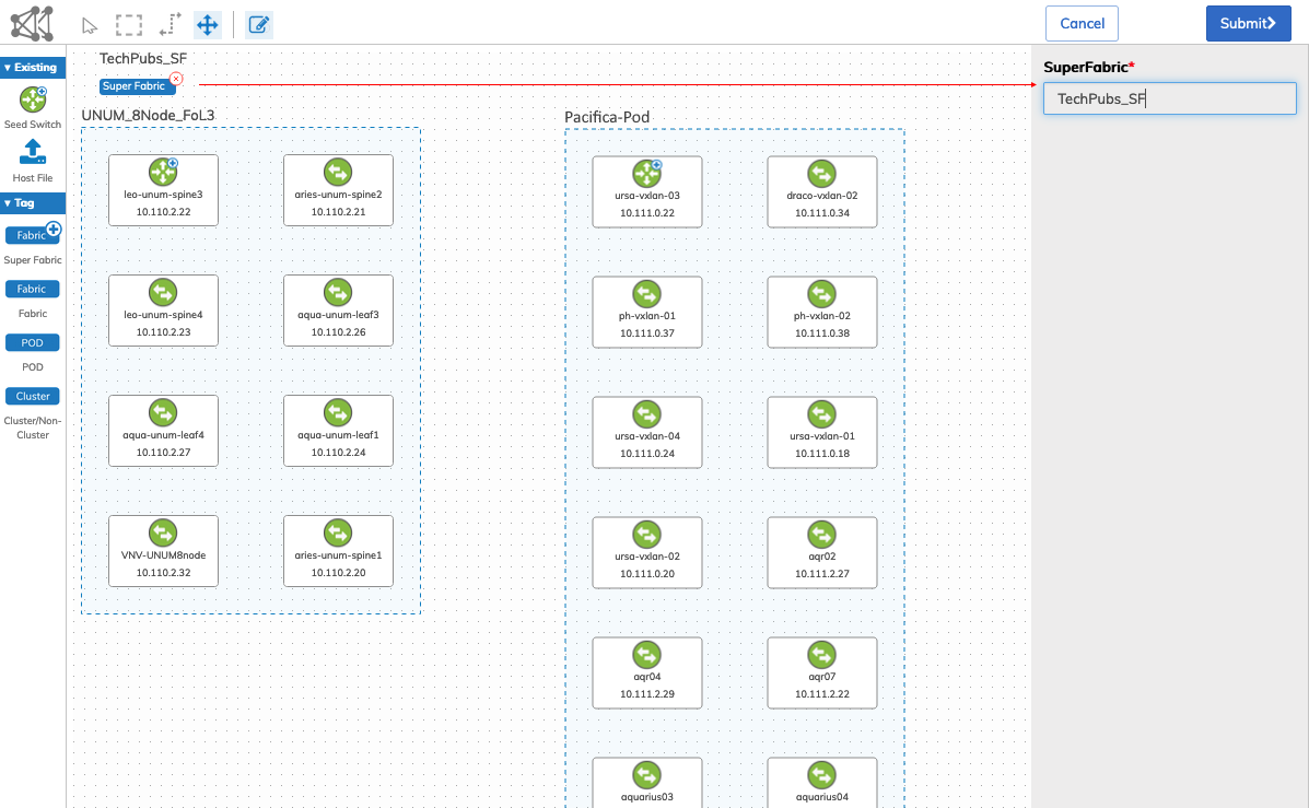
NetVisor UNUM Platform Global - Fabric Designer - Create Super Fabric Name
Click Submit to continue.
The NetVisor UNUM Dashboard displays a message confirming a successful creation of the seed switches.
Conversely, a warning message is displayed should the seed switch fail to be added. You should review all configuration parameters and try again in this event.
The Topology map updates with the added Super Fabric and runs a discovery process.
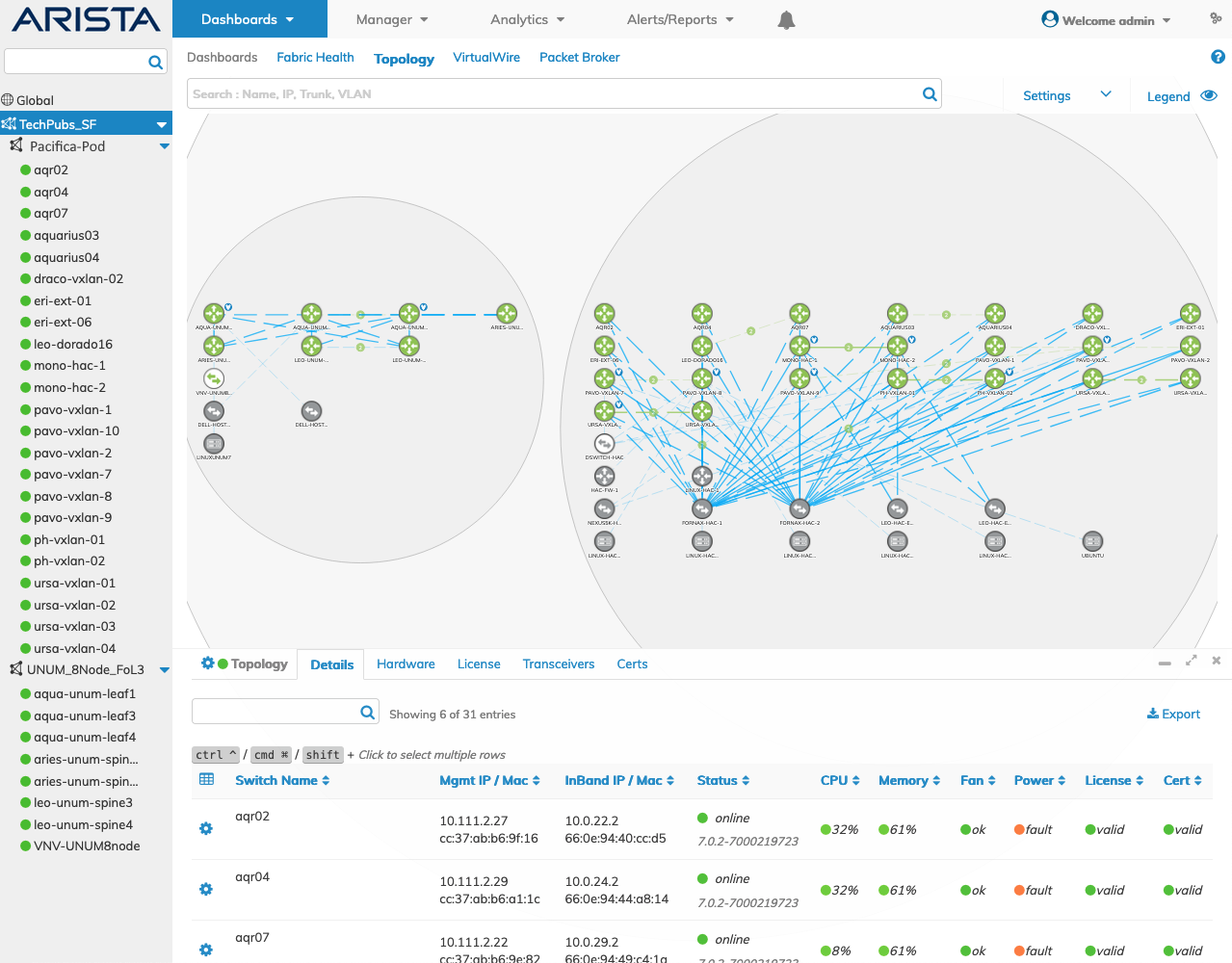
NetVisor UNUM Platform Global - Fabric Designer - Super Fabric Topology Map
Note the difference between the Super Fabric topology icon and a standard Fabric topology icon.
![]()
NetVisor UNUM Platform Global - Fabric Designer - Super Fabric Icon
For more information on resizing and highlighting specific pod details, refer to the Highlight Pod section of this documentation.
Note: The following features are not supported in Super Fabrics: VirtualWire, Manage Services vLE, Mesh Ping, Manager Layer 3 Subnet, and Manager Layer 3 VRF. When attempting to access these features in a Super Fabric, you will see a "This feature is not supported for selected fabric." warning message.
Please refer to the Topology section for more information about feature and functions of the Topology Dashboard.