
How To Create a VirtualWire
How To Create a VirtualWire
There are features and functions used in Arista NetVisor UNUM and Insight Analytics that are common throughout the user interface (UI). Please refer to the Common Functions section for more information on the use of these functions and features.
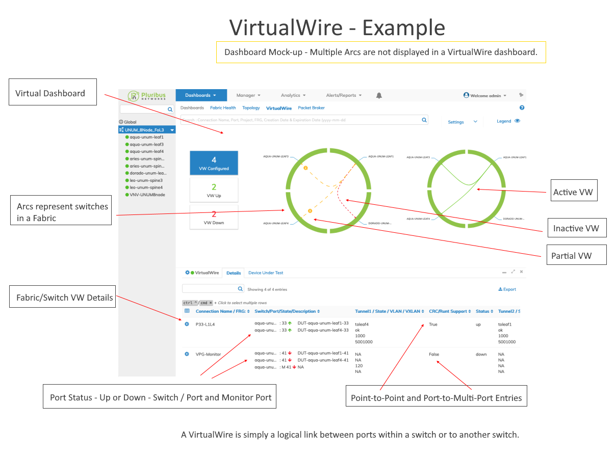
A VirtualWire (VW) is a logical link or tunnel between two fabric endpoints. A VW connect ports within a switch, or from a port on one switch to a port on a switch in another cluster. This feature provides a mechanism for link state tracking between two ports of two switches in the same fabric for VW.
The VW feature requires that a Layer-3 fabric must be deployed from a NetVisor UNUM Layer-3 Playbook. For further information on creating a Layer-3 Fabric please refer to Manager Fabric section.
NetVisor UNUM provides a "pick and choose" itemized list of VW settings for easy configuration.
Additional types of VW connections are possible and described in this use case. For more information, please refer to:
Manually Creating a VirtualWire on a Super Fabric
Creating a VirtualWire (Virtual Link Extension - vLE) Between Ports on the Same Switch
The general workflow in building a VW involves several basic steps:
Configuration Note: Whenever possible, physically cabling the devices to be connected to their respective ports before creating the vLE simplifies the process.
Caution: When creating an VirtualWire on a port with existing VLANs, any existing VLANs will be removed from the port. Removal of these ports can be traffic-impacting. Before proceeding, verify that the port does not have existing VLANs configured when creating an VirtualWire.
|
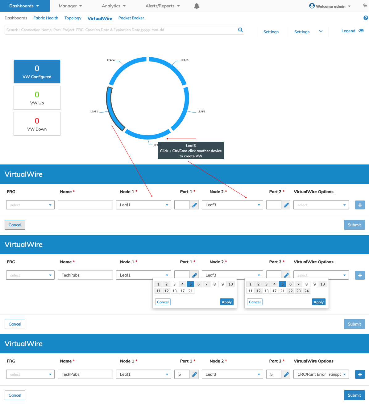
Create a Virtual Link Extension Use the following method to create a vLE: 1)Create the requisite tunnels before configuring the vLE on each switch where a tunnel is required. For example:
2)From the Overlay ring graphic in the dashboard hold the Control or Command key on your keyboard and click on two switches represented by colored arcs in the ring. The vLE Connection dashboard opens and you enter the applicable configuration parameters. 3)Provide a meaningful name, such as Leaf1p30-L3p30, where the vLE will connect Leaf1, Port 30 to Leaf3, Port30. 4)Complete the connection between devices by cabling both ends of the vLE to their respective devices (unless this was already done). 5)Trigger a vLE discovery from thevLE VirtualWire (VirtualWire → VirtualWire details → Gear button → Trigger vLE discovery). At this point the vLE inter-link connection in the ring diagram updates reflecting the new vLE connection. Changes in the inter-link visual indicators from Green to Red, or vice versa, indicate whether ports are "up" or "down". In either case, the vLE is created and displayed in the dashboard. Bringing the ports "up" and ensuring the Tunnel is "up" changes the vLE status to Up. If the inter-link connection stays Red, please verify that the port(s) state is up and the respective devices are connected and active. Configuration Note: Using a ZTP configuration automates tunnel creation and negates the need for manually creating tunnels. Therefore, Step 1, described above, is unnecessary. |
Interactively Manage vLE via the Dashboard
As shown in the following example, you click on a switch (LEAF113) which highlights. While holding the Control or Command key on your keyboard select a second switch (LEAF133). The vLE Connection dashboard opens and you enter the applicable configuration parameters.
Click Submit to continue or Cancel to return to the previous screen without making any changes.
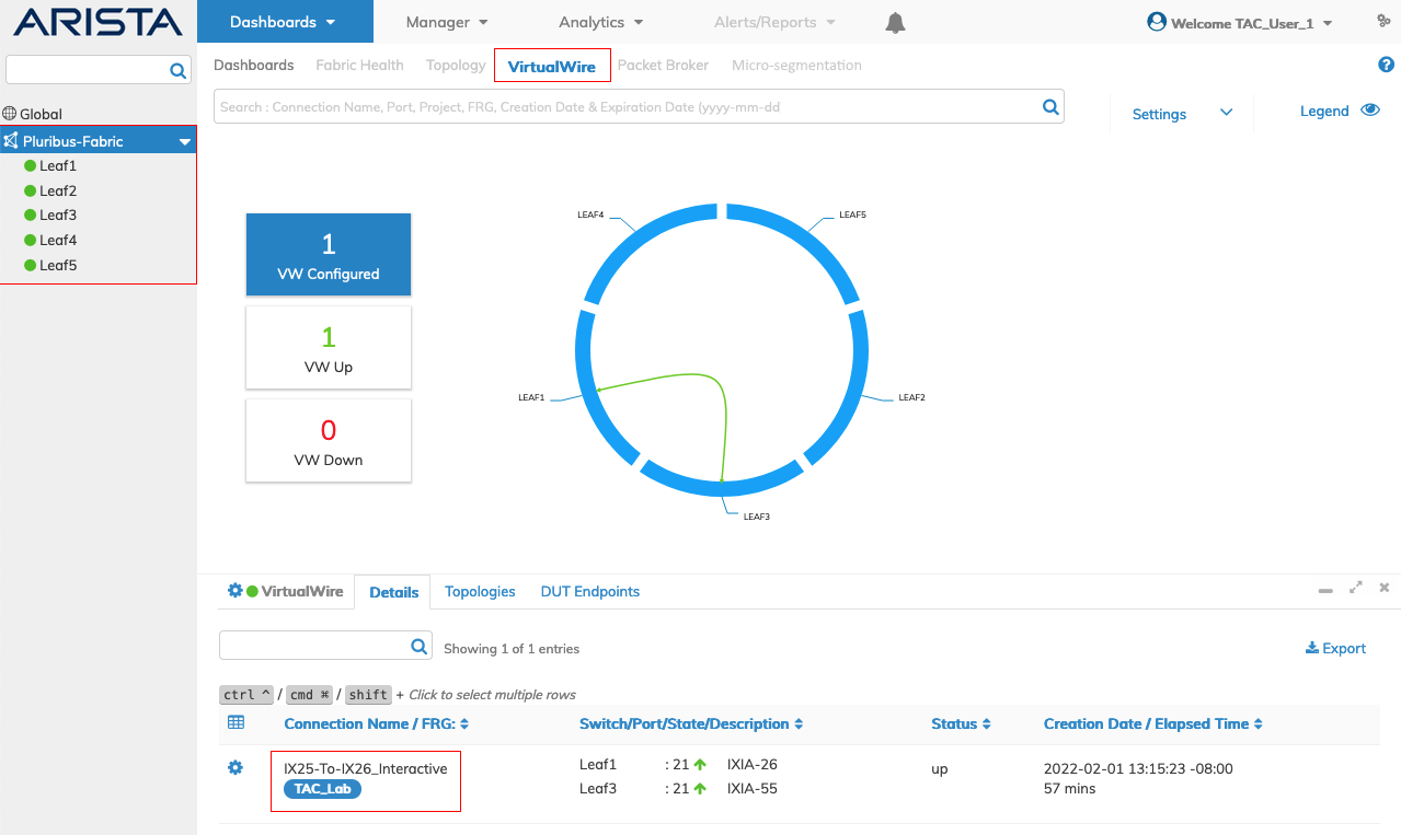
VirtualWire Dashboard - Interactive VirtualWire
The VirtualWire displays in the dashboard.
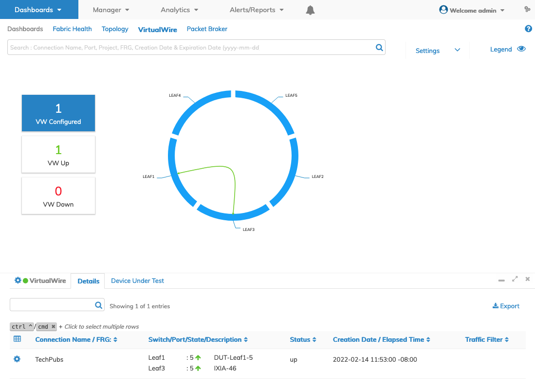
VirtualWire Dashboard - Interactive VirtualWire Created
VirtualWire Dashboard - Explanation
Virtual Link Extension - Example
Add Device Under Test
Primarily intended for lab automation, Device Under Test (DUT) allows the lab network administrator to configure ports connected to tools and devices under test. Custom descriptions are allowed and searchable.
To configure DUT use the Cog ![]() icon and select Add Device Under Test.
icon and select Add Device Under Test.
Select the applicable switch from the drop-down menu.
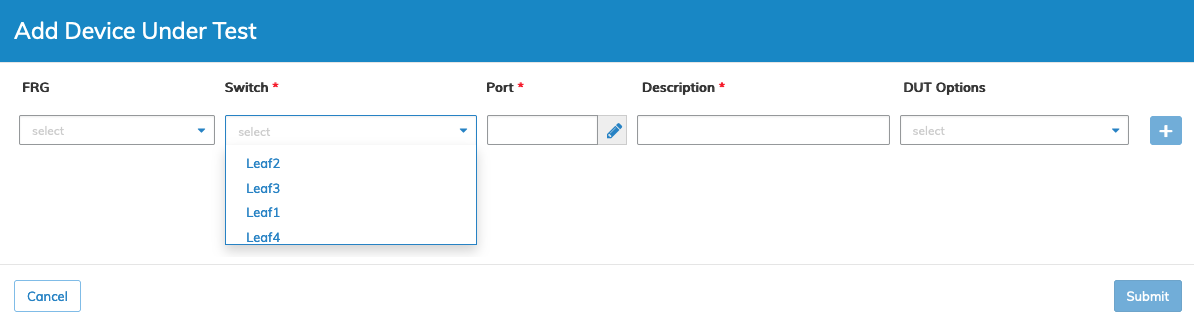
Dashboards VirtualWire - Device Under Test - Add Device Under Test - Select Switch
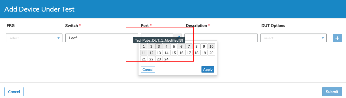
Select the applicable port from using the Interactive Port Selector. The widget displays a grid accurately representing switch port availability and shows the number of physical ports on a given switch.
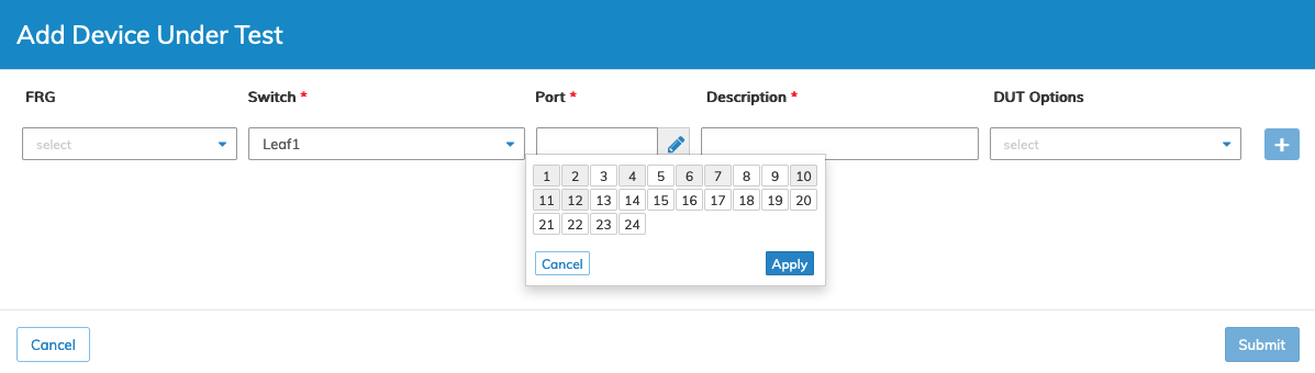
Dashboards VirtualWire - Device Under Test - Add Device Under Test - Port Selector
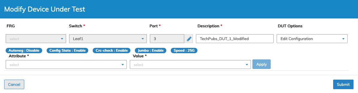
Enter a Description for the DUT. Select an applicable DUT Option and click the ![]() icon. The selected option and value displays in the configuration dashboard.
icon. The selected option and value displays in the configuration dashboard.
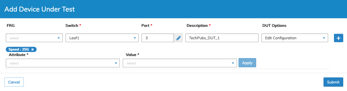
Dashboards VirtualWire - Device Under Test - Add Device Under Test
Click Submit to continue or Cancel to return to the previous screen without making any changes.
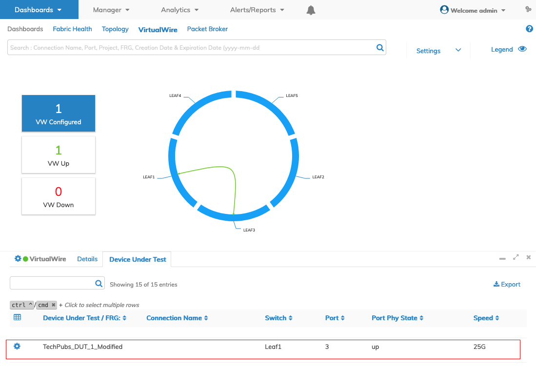
The Device Under Test Tab lists the new DUT.
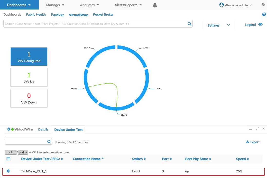
Dashboards VirtualWire - Device Under Test - Updated Dashboard
The Device Under Test dashboard differs from the Details dashboard and displays the following parameter details:
•Device Under Test / FRG
•Project
•Switch
•Port
•Bezel Port
•Config State
•Port_Phy_State
•Port_Mac
•Speed
•Eth_mode
•VLANs
•Active_VLAN
Search DUT
Search for devices by entering your search criteria. The dashboard updates with the results. Click the ![]() icon to clear the search box.
icon to clear the search box.
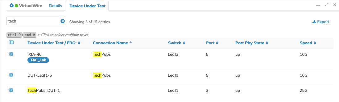
Dashboards VirtualWire - Device Under Test - Search Results Dashboard
Adding a Port Description
To add or change a description use the Cog ![]() icon and select Edit.
icon and select Edit.

Dashboards VirtualWire - Device Under Test - Add Port Description
Add or update the description.
Dashboards VirtualWire - Device Under Test - Update a Port Description
Click Submit to continue or Cancel to return to the previous screen without making any changes.
On the VirtualWire dashboard click Trigger vLE Discovery in the VirtualWire Details pane.
The Details pane updates with the new port description after completing the discovery process. Note the addition of a second vLE between the two switches.
Dashboards VirtualWire Dashboard - Interactive vLE Manage - Port Description Added Example
Subsequent use of Interactively Manage vLE via the Dashboard reveals the Port and Port Description in the drop-down selection fields.
Dashboards VirtualWire Dashboard - Interactive vLE Manage - Port Description - Available in Port Selector
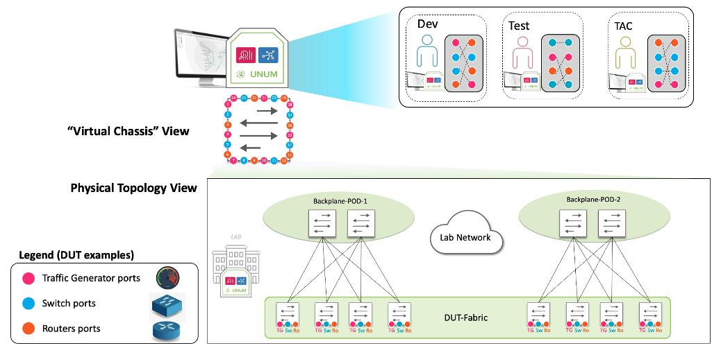
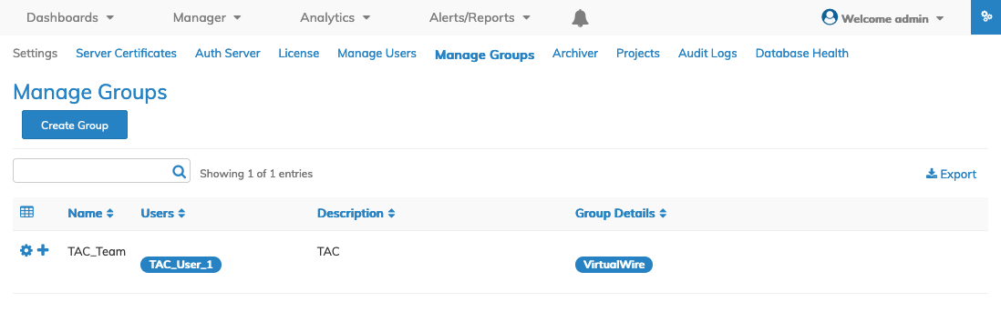
Multi-Tenancy VirtualWire
Fabric ports can be grouped and assigned to lab users or Tenants, for example, Development, Test, or TAC (Technical Assistance Center) Teams. Each user is isolated and can independently manage Device Under Test (DUT) end-points and associated VirtualWires.
VirtualWire - VirtualWire Multi-Tenancy
Use Manage Groups to create and manage a User Group (UG) and Fabric Resource Group (FRG).
In the following example, the TAC-Team UG is assigned access to the VirtualWire dashboard and a user assigned a role.
VirtualWire - VirtualWire User Group
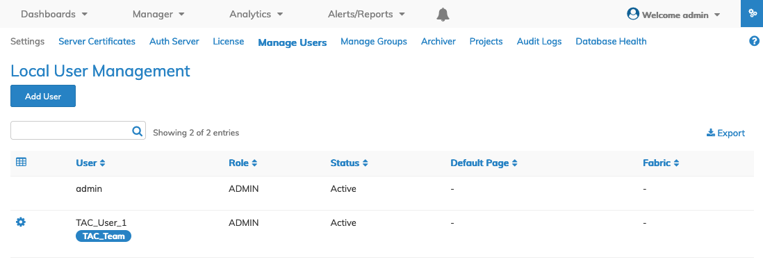
Use Manage Users to create and assign roles.
VirtualWire - VirtualWire User Role
Create the FRG and assign them to the UG.
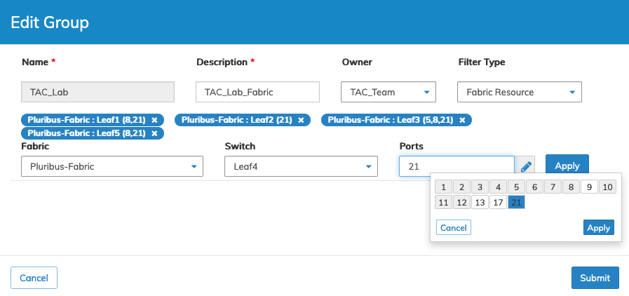
VirtualWire - Fabric Resource Group
Click Submit to continue.
The FRG appears on the dashboard.
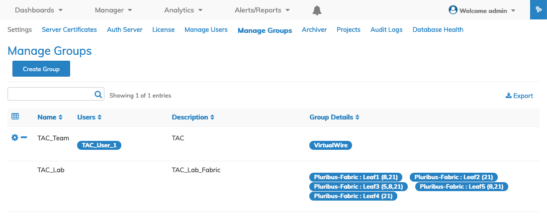
VirtualWire - Fabric Resource Group Manage Groups Dashboard
When TAC_User_1 logs in to NetVisor UNUM they are presented with their tenant dashboard limited to VirtualWire and the assigned Fabric and resources.
VirtualWire - Tenant Dashboard
Manually Creating a VirtualWire on a Super Fabric
It is possible to create a VirtualWire (VW) connection in a Super Fabric between the two Pods comprising the Super Fabric.
However, once constructed, the link is not viewable in the VW dashboard. Use the Port Stats feature to view traffic flowing across the connection.
Example Instructions
1)Create VLAN 333 (any available VLAN number is acceptable) for the Tunnel interface with the Scope set to local and no ports. Perform this step on the two switches being used to construct the VW.
2)Add a vRouter interface to VLAN 333. Use different networks on Switch 1 and Switch 2. The vRouter interface will initially be down.
3)Create the Tunnel from Switch 1 and Switch 2 using the two Network IP addresses assigned to VLAN 333.
4)Verify both the Tunnel and the vRouter interface are Up.
5)Create a second VLAN 300 (any available VLAN number is acceptable) with VXLAN 300300 in transparent mode on both switches. Assign the port to this VLAN where the host or an Ixia port connects.
6)Map the VLAN to the Tunnel and verify the mapping is successful.
7)Create a VTEP on each switch being used to construct the VirtualWire.
8)Verify the VW is working by sending traffic across it and viewing the link using Port Stats.
Creating a VirtualWire (Virtual Link Extension - vLE) Between Ports on the Same Switch
Creating a VW (vLE) between ports on the same switch may be desirable, depending on your specific requirements.
Create the VW using the VirtualWire Dashboard or the Manager Layer 2 VLAN / L2 OVL - Manage vLE dashboard.
Creating a single point-to-point VW from the VirtualWire Dashboard requires using the Create Point-To-Point VirtualWire feature and selecting the CRC/Runt Error Transport configuration option.
CRC/Runt Error Transport – Makes a point-to-point VirtualWire transparent to CRC errors and Runt (under-size) frames.
Caution: This is not the default selection; you must select the option from the drop-down menu. Unless you specifically select the CRC/Runt Error Transport option, you will create a vPG connection, and the vLE connection between ports on the same switch will not function. Using this option, UNUM creates the vLE with no vPG connections.
Creating the VW using the Manager Layer 2 VLAN / L2 OVL - Manage vLE dashboard also creates a vLE with no vPG connections.
Note: In either case, UNUM automatically creates the requisite transparent vLANS. There is no need to create vLANs manually.