
Add a VirtualWire
VirtualWire - Creating a VirtualWire
There are features and functions used in UNUM Manager and UNUM Analytics that are common throughout the user interface (UI). Please refer to the Common Functions section for more information on the use of these functions and features.
Configuration Note: Whenever possible, physically cabling the devices to be connected to their respective ports before creating the VW simplifies the process.
Caution: When creating an VirtualWire on a port with existing VLANs, any existing VLANs will be removed from the port. Removal of these ports can be traffic-impacting. Before proceeding, verify that the port does not have existing VLANs configured when creating an VirtualWire.
Building VirtualWires
There are various options available to build VWs (VirtualWires), depending on your specific needs and requirements. These include:
•DUT Endpoints – Primarily intended for lab automation, this method allows the lab network administrator to configure ports connected to tools and devices under test.
•Build VirtualWire Using Search Feature – Uses a convenient search method to locate switches and their associated ports in more complex topologies to configure VWs.
•Build VirtualWire Using Topology Ring – Employs an interactive method to create VWs between two switches in a Fabric using the Topology map.
•Ad Hoc VirtualWire Creation – Utilizes a manual method for building tunnels and configuring VWs when only one or two connections are required.
•Super FabricVirtualWire – Manually create a VW on a Super Fabric. Creates a VW connection between the Pods in a Super Fabric.
VirtualWire Considerations
You may create VWs from ports between leafs across a switch cluster or between leafs in the same Fabric. However, you cannot create VWs on ports that exist in the same leaf or between leafs belonging to different Fabrics.
General Workflow
The workflow in building a VW involves several steps as outlined below. In general, there are three steps for creating a VW:
1.Create the Fabric Underlay Network manually or use an L3 Playbook. The process is well documented in the Fabric Creation Guide.
Configured Fabric
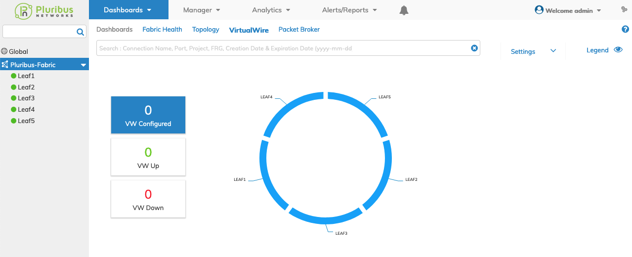
VirtualWire - Configured Fabric
2.Build the inventory of DUT's (Devices Under Test) and their physical connections to the L1 Fabric. This step is only performed once during the initial setup. From the VirtualWire dashboard use the Add Device Under Test function and map each DUT name to the Switch and Port in the respective L1 Fabric.
DUT Inventory
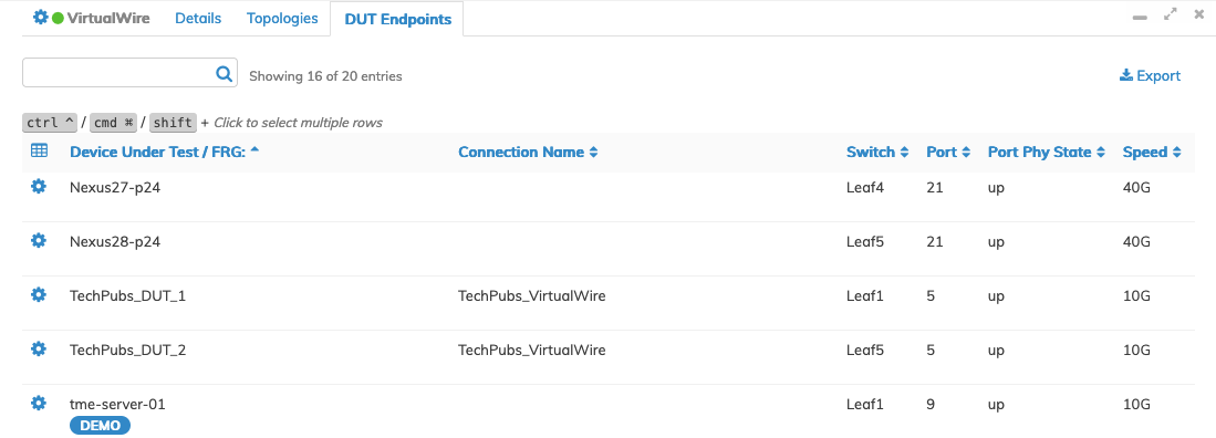
VirtualWire - DUT Inventory
3.Establish connections across the DUTs. Provision a VirtualWire from the dashboard using the DUT names in the inventory. Optionally, provision advanced Virtual features.
Create Point-to-Point VW using Search & Filter
Enter the DUT names in the Search box.
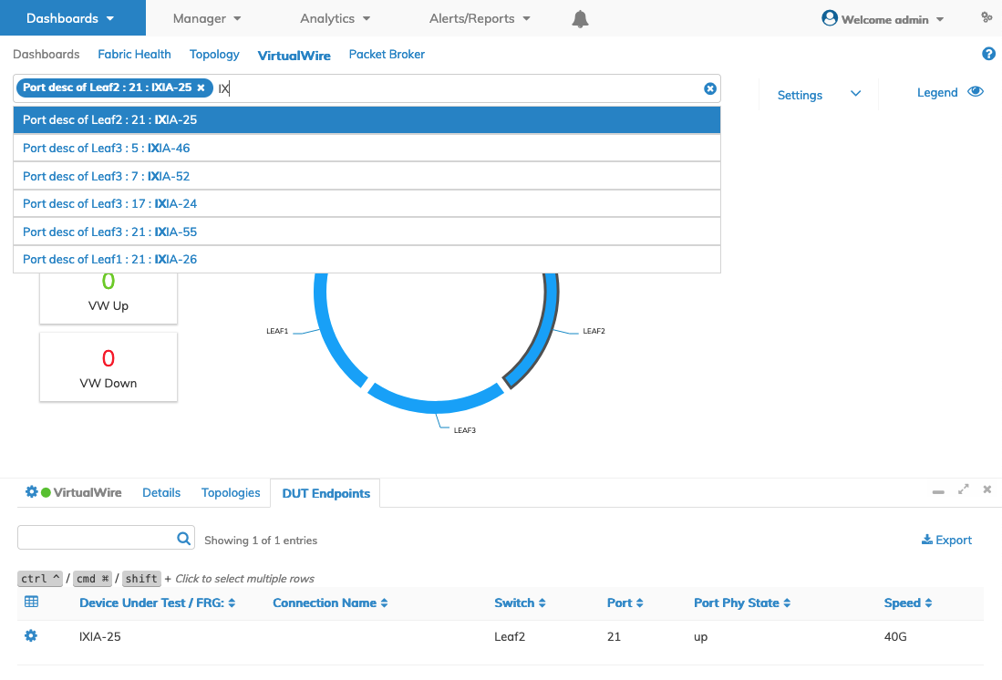
VirtualWire - Create VirtualWire - Search & Filter - Criteria
After entering the second DUT the VirtualWire windows appears with pre-populated parameters including the respective ports.
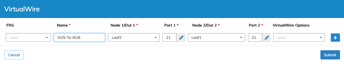
VirtualWire - Create VirtualWire - Search & Filter Populated
For a basic point-to-point connection, provide a name and click Submit. Otherwise, select Cancel to return to the previous screen without making any changes.
The dashboard updates with the new VW connection providing details about the Connection Name, Switch/Port/State/Description, Status, Creation Date/Elapsed Time and, Traffic Filter.
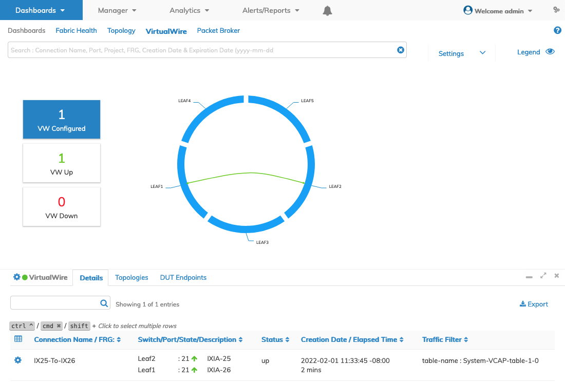
VirtualWire -Point-to-Point VirtualWire Connection
The inter-link connection colors denote VirtualWire status.
•Red Dashed Line – All Down - indicates all VWs are down.
•Green Solid Line – All Up - indicates all VWs are up.
•Yellow Dashed Line – Partial Up - indicates a mix of Up/Down connections.
•![]() – Port Down - indicates a Port Down condition.
– Port Down - indicates a Port Down condition.
At this point the VW inter-link connection in the ring diagram updates reflecting the new VW connection. Changes in the inter-link visual indicators from Green to Red, or vice versa, indicate whether ports are "up" or "down". In either case, the VW is created and displayed in the dashboard. Bringing the ports "up" and ensuring the Tunnel is "up" changes the VW status to Up. If the inter-link connection stays Red, please verify that the port(s) state is up and the respective devices are connected and active.
VirtualWire Options
When more advanced VirtualWire capabilities are required, use the VirtualWire Options menu that includes:
•P2MP – Allows the creation of a point-to-multi-point or one-to-many VirtualWire (e.g., sharing a traffic generator across many devices). Limited to 512 connections.
•CRC/Runt Error Transport – Makes a point-to-point VirtualWire transparent to CRC errors and Runt (under-size) frames.
•Monitor Mode – Provides the ability to mirror the traffic on the VirtualWire to one or more remote monitoring/security tools. Limited to 512 connections.
•Add Traffic Filter – Allows the basic filtering of VirtualWire traffic based on a 5-tuple (VLAN, Source IP, Destination IP, Protocol, L4 Port) list. Limited to 512 connections.
•Expiration Date – Adds a timer to the VirtualWire, which upon expiration will automatically delete the VirtualWire and free up the resources.
•Project – Please refer to the Settings - Projects section for more information on creating projects.
Note: VirtualWire is limited to 512 connections. If more than 512 VirtualWire connections are required, use Manage Topology vLE or the CRC/Runt option.
The following examples demonstrate several of the VirtualWire advanced options.
P2MP - Point-To-Multi-Point with Monitor Mode
To configure the Point-To-Multi-Point, use the Cog ![]() icon and select Add VirtualWire.
icon and select Add VirtualWire.
Enter the Name, Node 1, Port 1, Node 2, Port 2 values and select Monitor Mode from the VirtualWire Options menu. Enter the Mon Node and Mon Port values and click Apply. Add optional filtering steps by entering the values in the respective parameter boxes and clicking Apply.
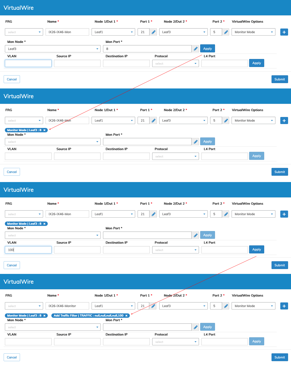
VirtualWire Point-to-Multi-Point with Monitor - VirtualWire Connection
When complete, click Submit.
As illustrated in the following example the Monitor_Tool1 is connected to Leaf3 Port 8 with VLAN 100 set as an optional filter.
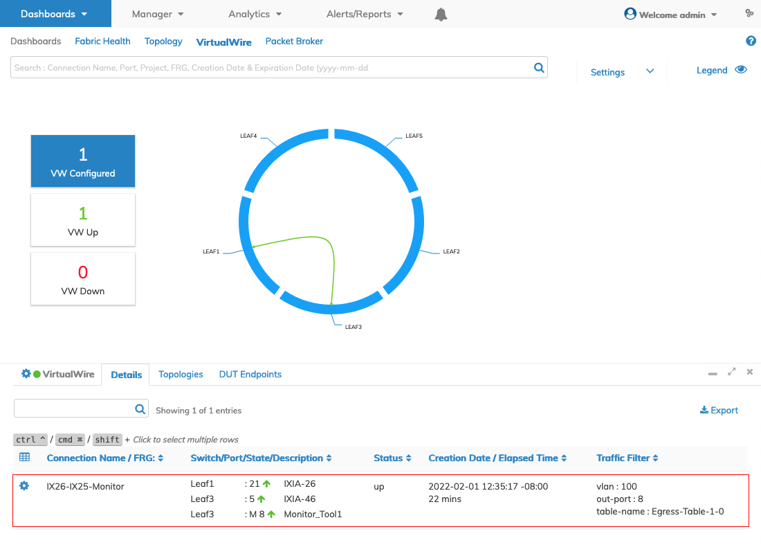
VirtualWire Point-to-Multi-Point with Monitor - VirtualWire Connection Dashboard
Note: Multiple monitoring ports can be configured depending on your requirements.
Create Point-To-Point VirtualWire - Topology Interactive Mode
As shown in the following example, click on a switch (Leaf1) which highlights. While holding the Control or Command key on your keyboard select a second switch (Leaf3).
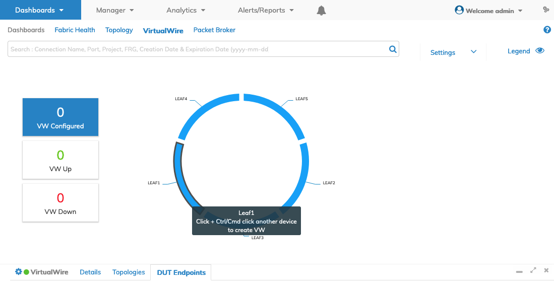
VirtualWire Point-to-Point Using Topology - Select Nodes
Enter the required parameters, Name, Port 1, and Port 2 and select CRC/Runt Error Transparency from the VirtualWire Options menu.
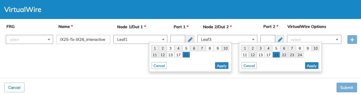
VirtualWire - Point-to-Point Using Topology - VirtualWire Connection Parameters - Interactive Port Selector
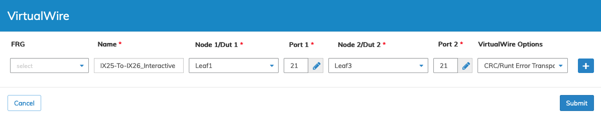
VirtualWire - Point-to-Point Using Topology - VirtualWire Connection Parameters
Click Submit to continue or click Cancel to return to the previous screen without making any changes.
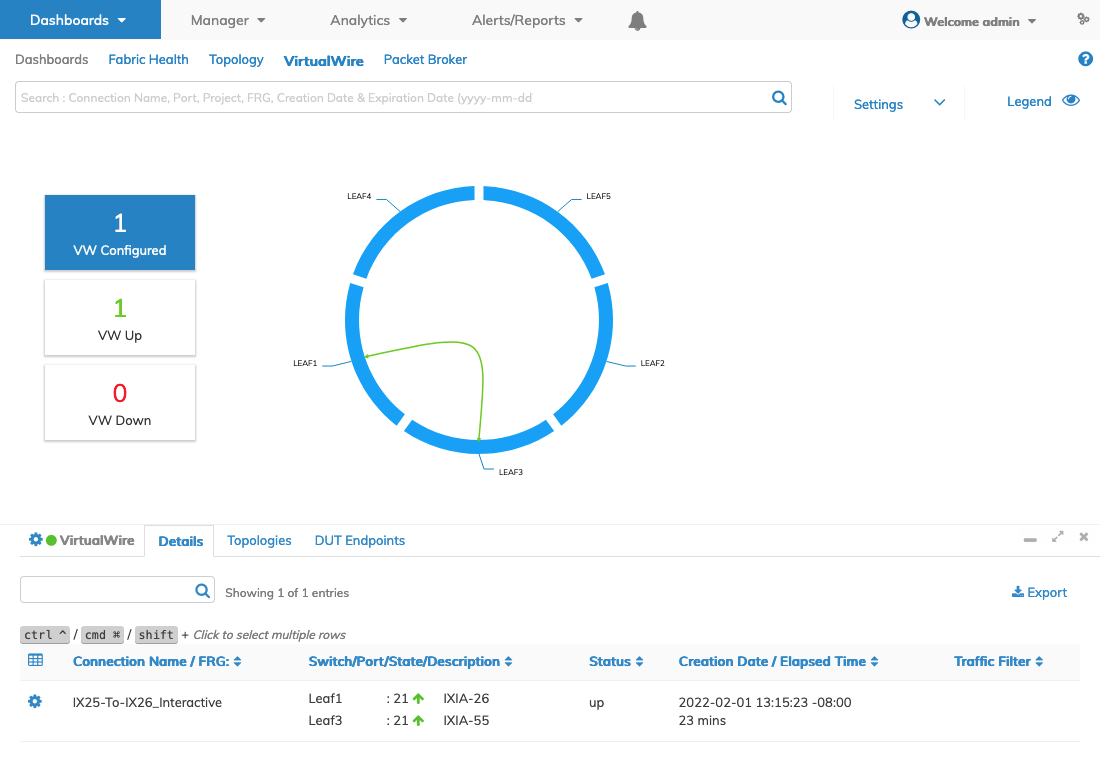
VirtualWire - Point-to-Point Using Topology - VirtualWire Connection Dashboard
DUT Port Descriptions
Select switch nodes and Device Under Test (DUT) names from the drop-down lists under the Node 1/DUT 1 and Node 2/DUT 2 selectors. When selecting a DUT, the port entry is auto-populated from the previously created DUT.
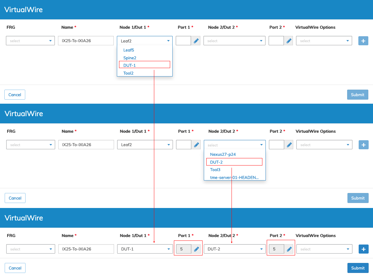
VirtualWire - Create VirtualWire - DUT Names & Ports
DUTs are searchable from the details pane.
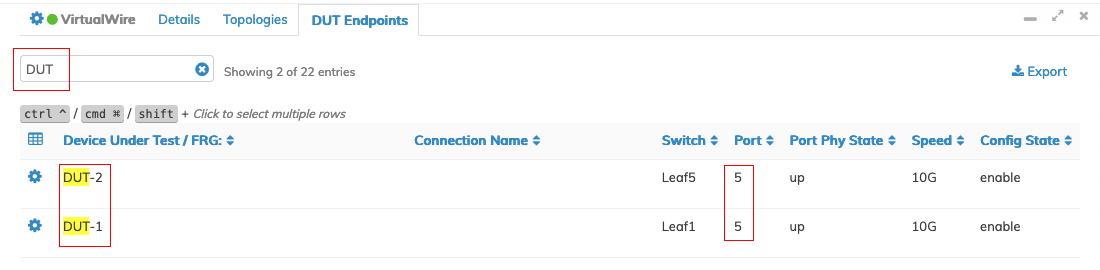
VirtualWire - Create VirtualWire - Search DUTs
Multi-Tenancy VirtualWire
Fabric ports can be grouped and assigned to lab users or Tenants, for example, Development, Test, or TAC (Technical Assistance Center) Teams. Each user is isolated and can independently manage Device Under Test (DUT) end-points and associated VirtualWires.
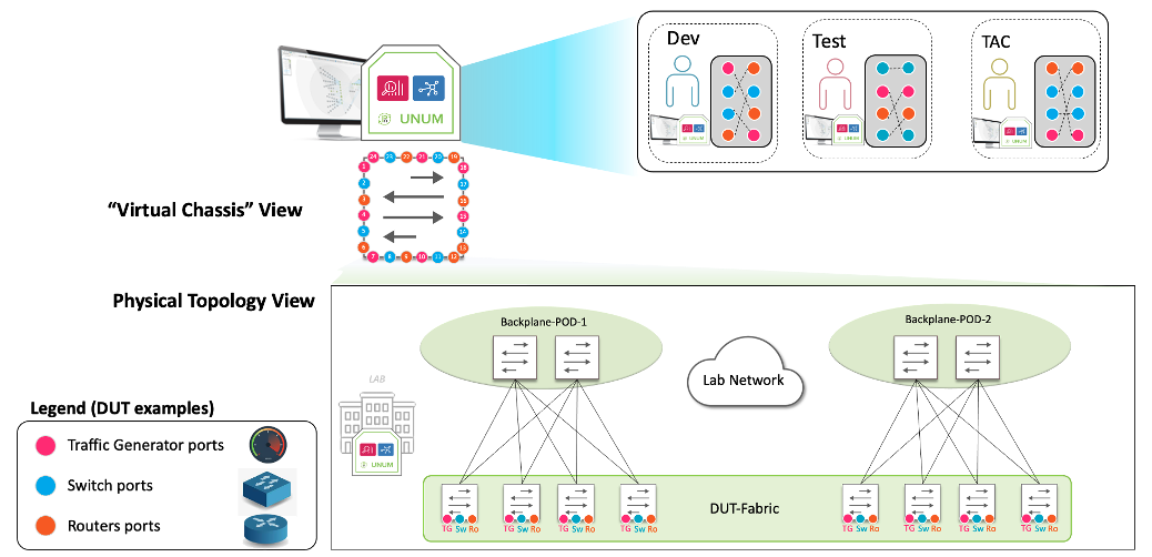
VirtualWire - VirtualWire Multi-Tenancy
Use Manage Groups to create and manage a User Group (UG) and Fabric Resource Group (FRG).
In the following example, the TAC-Team UG is assigned access to the VirtualWire dashboard and a user assigned a role.
VirtualWire - VirtualWire User Group
Use Manage Users to create and assign roles.
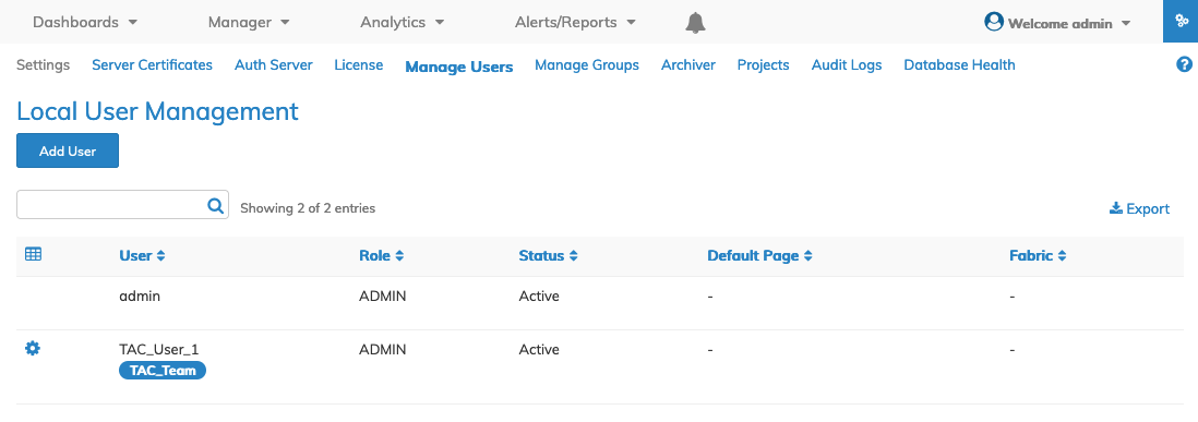
VirtualWire - VirtualWire User Role
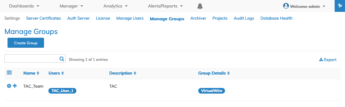
Create the FRG and assign them to the UG.
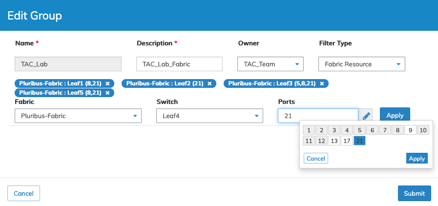
VirtualWire - Fabric Resource Group
Click Submit to continue.
The FRG appears on the dashboard.
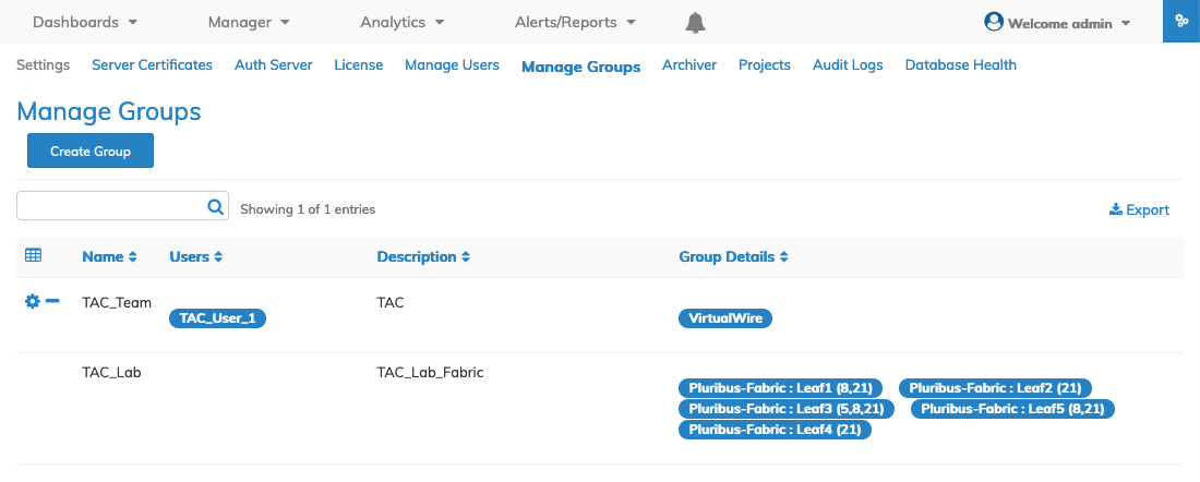
VirtualWire - Fabric Resource Group Manage Groups Dashboard
When TAC_User_1 logs in to UNUM they are presented with their tenant dashboard limited to VirtualWire and the assigned Fabric and resources.
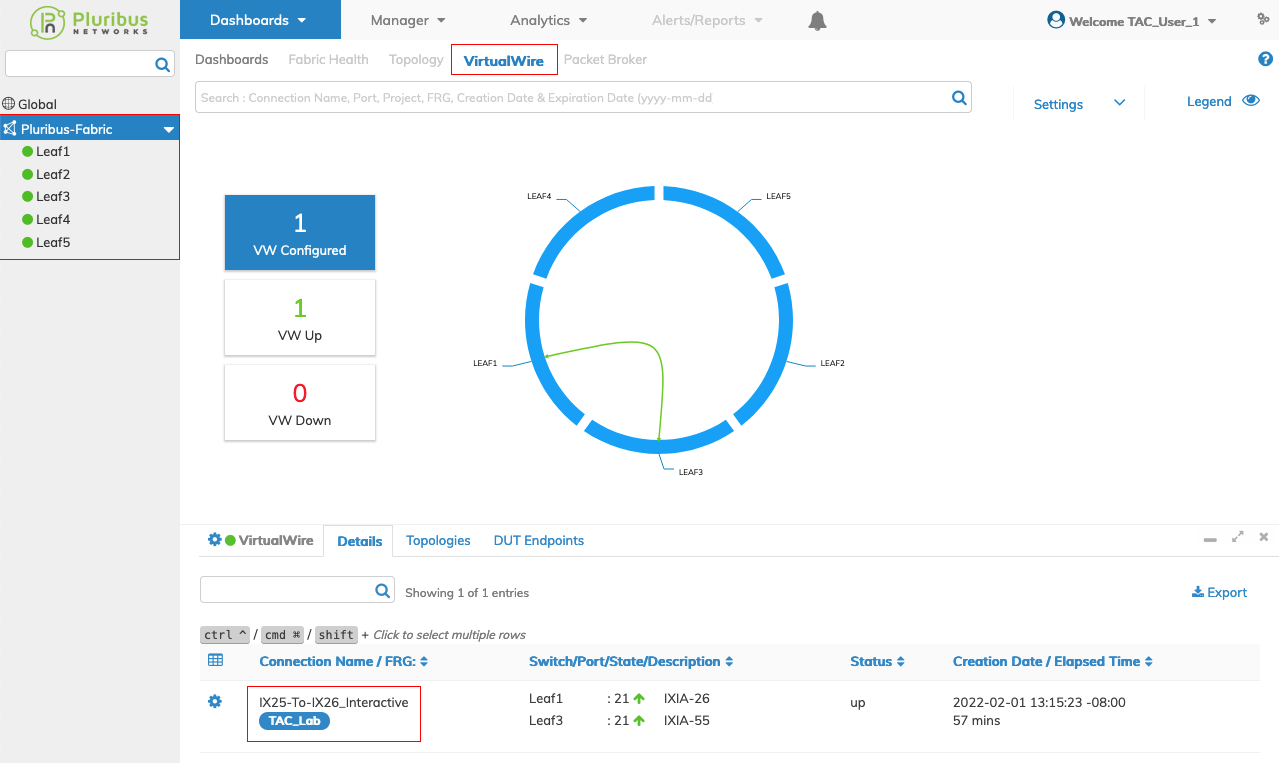
VirtualWire - Tenant Dashboard