
Virtual Topology - Manage Topology vLink
Fabric Layer 1 – Virtual Topology - Manage Topology vLink
There are features and functions used in UNUM Manager and UNUM Analytics that are common throughout the user interface (UI). Please refer to the Common Functions section for more information on the use of these functions and features.
Manage Topology vLink
Please refer to the Packet Broker and VirtualWire sections for more information about vPGs.
Selecting Manager → Layer 1 → Virtual Topology → Manage Topology vLink displays the Manage Topology vLink dashboard with a list of any existing vLink entries.
Note: If no entries exist a "No Data Exists" message is displayed. You must first configure an entry on a switch. Prerequisite settings and configuration may be required.
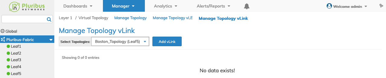
Manager Virtual Topology - Manage Topology vLink - Fabric Dashboard - No vLinks
Add a vLink
After creating a virtual topology using Manage Topology, select the topology from the drop-down list.
|
Usage Notes: |
1.The virtual topology must be disabled before adding, modifying, or deleting a vLink. Refer to the Manage Topology section for more information. |
|
2.The vPGs that are part of a topology must be present in the fabric before enabling the topology. UNUM raises an error if you try to enable a topology for vPGs that do not exist. |
|
|
3.Netvisor ONE supports topologies with vFlows having fabric scope only. |
|
|
4.Two or more vFlows with a common bidirectional vPG are not supported. |
|
|
5.vPGs must be bi-directional. You cannot specify source or destinations as endpoints of a vLink. |
Select Add vLink and enter the requisite parameters, which include:
•Switch – Select a Switch.
•Topologies – Pre-populated from drop-down list selection.
•EndPoint 1 – Select a VPG from the drop-down list.
•EndPoint 2 – Select VPG from the drop-down list.
•vLink Name – Provide a name for the vLink.
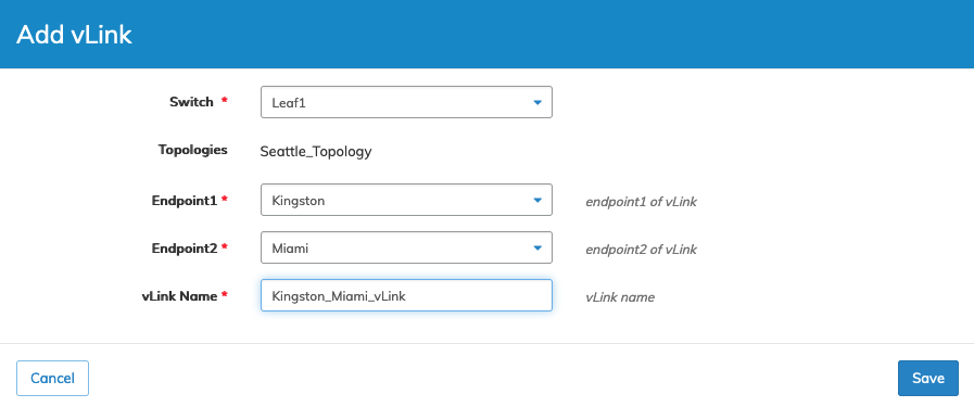
Manager Virtual Topology - Manage Topology vLink - Create a vLink
Click Save to continue or Cancel to return to the previous screen without making any changes.
The dashboard updates with the new vLink.
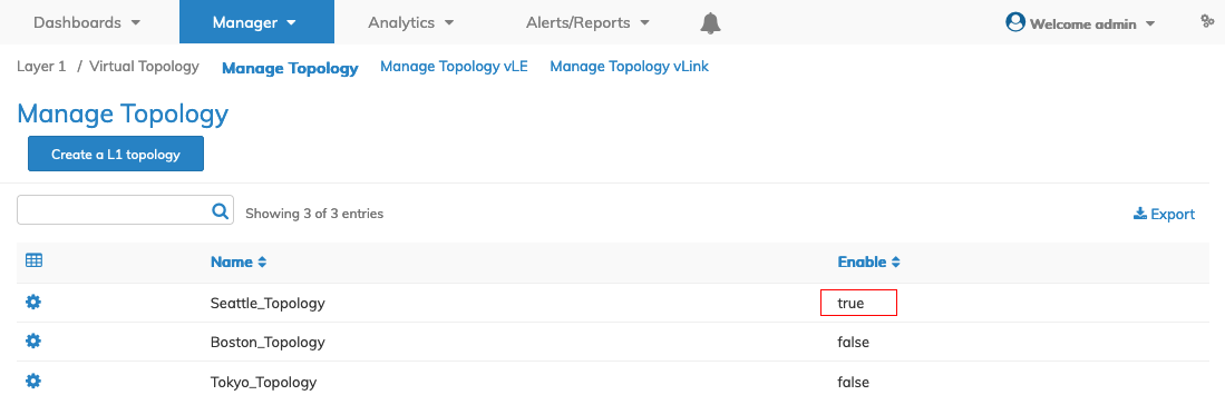
Select the applicable Fabric from the left-hand navigation bar and the dashboard updates showing all vLink entries from all switches within the Fabric.
Select Topologies All. The dashboard displays a list of existing Topology entries by Fabric and Switch.
Additional parameters include: Topologies, vLink Name, Endpoint 1, and Endpoint 2.
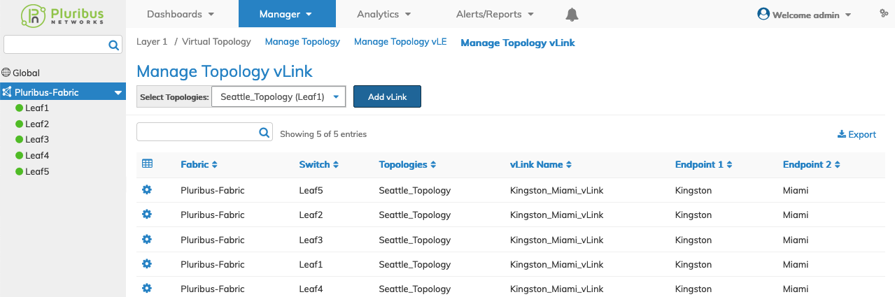
Manager Virtual Topology - Manage Topology vLink - Fabric Dashboard - vLinks
Select the applicable switch from the fabric and the dashboard updates automatically with the switch vLink entries.
The dashboard displays a list of existing Topology entries by Topology name.
Additional parameters include: vLink Name, Endpoint 1, and Endpoint 2.

Manager Virtual Topology - Manage Topology vLink - Switch Dashboard - vLinks
Edit a vLink
Select Edit using the Cog ![]() icon and update as required. Parameters include:
icon and update as required. Parameters include:
•Endpoint 1 – Endpoint 1 of vLink.
•Endpoint 2 – Endpoint 2 of vLink.
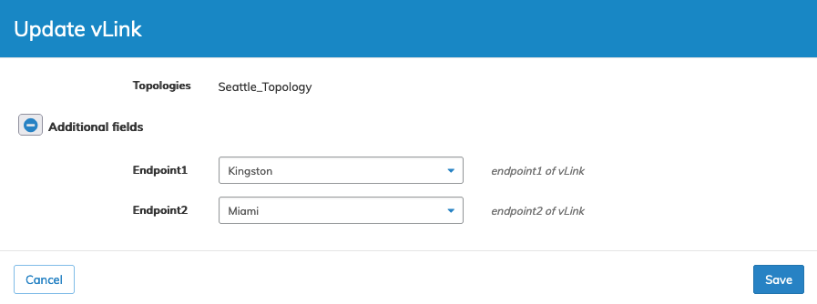
Manager Virtual Topology - Manage Topology vLink - Edit vLinks
Click Save to continue or Cancel to return to the previous screen without making any changes.
Enable the vLink
Using the Manage Topology dashboard, select an entry and enable a topology using the Cog ![]() icon and checking Enable.
icon and checking Enable.
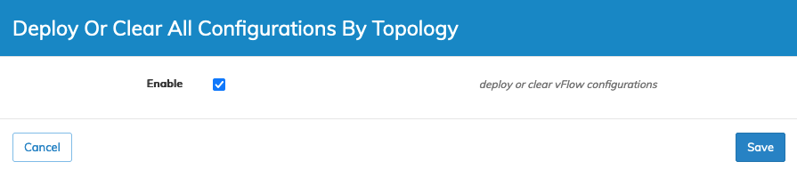
Manager Virtual Topology - Manage Topology vLink - Deploy the vFlow
Click Save to continue or Cancel to return to the previous screen without making any changes.
Note: Attempting to enable a virtual topology after adding a vLE without building the requisite underlay and overlay results in an error message being displayed. Please refer to the VirtualWire section for more information.
Manager Virtual Topology - Manage Topology vLink - Enable the vLink
The vLink appears in the VirtualWire dashboard.
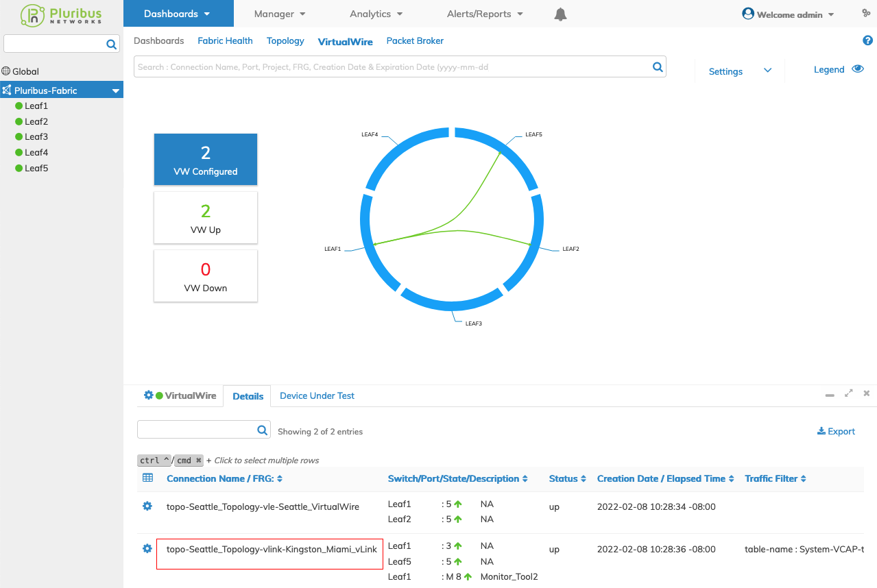
Manager Virtual Topology - Manage Topology vLink -VirtualWire Dashboard
Note: VirtualWire is limited to 512 connections. If more than 512 VirtualWire connections are required, use Manage Topology vLE or the CRC/Runt option in the VirtualWire dashboard.
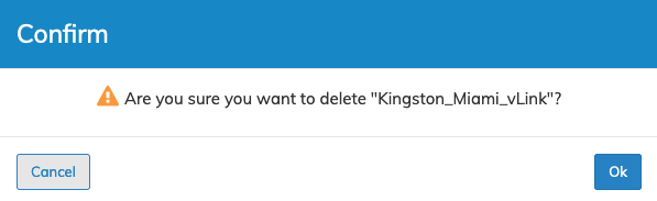
Delete a vLink
If enabled, you must first disable a topology to delete a vLink. Refer to Manage Topology for more information.
Select Delete using the Cog ![]() icon and delete the vLink. Confirm the deletion.
icon and delete the vLink. Confirm the deletion.
Manager Virtual Topology - Manage Topology vLink - Delete vLink